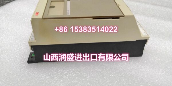
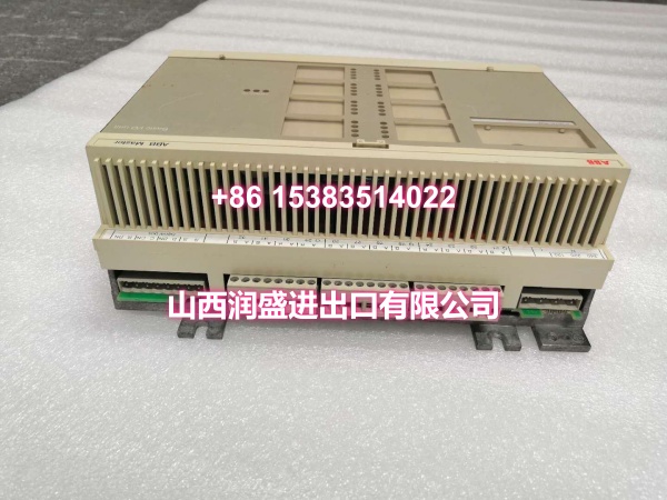
Product Core Brief
- Model: DSDX452
- Brand: ABB
- Series: ABB Advant Master / S100 Series
- Core Function: Digital input/output combo module that consolidates both digital input and digital output channels in a single unit, reducing rack slot usage and simplifying wiring for mixed I/O applications.
- Product Type: Digital Input/Output Combo Module
- Key Specs: Combined Digital Input & Output Channels | 24VDC | Optical Isolation | LED Status Indicators | Rack-Mount Form Factor | Comprehensive Self-Diagnostics
- Note: Condition: New Original (New Surplus). Origin: Sweden.
Key Technical Specifications
| Parameter | Value |
|---|---|
| Device Model | |
| Brand | ABB |
| Series | ABB Advant Master / S100 Series |
| Function | Combined digital input and output signal processing |
| Product Type | Digital I/O Combo Module |
| Input Type | 24VDC digital inputs (optically isolated) |
| Output Type | 24VDC digital outputs |
| Power Supply | 24VDC (supplied by I/O rack backplane) |
| Isolation | Optical isolation between field circuits and backplane |
| Operating Temperature | Industrial-grade (typically 0°C to +55°C) |
| Cooling Method | Passive (air-cooled) |
| Mounting | Rack-mount (Advant Master / S100 backplane) |
| Features | LED status indicators per channel, comprehensive self-diagnostics, fault reporting |
| Typical Applications | Process control, manufacturing, power generation, oil & gas, chemical processing |
| Origin | Sweden |
| Condition | New Original (New Surplus) |
Product Introduction
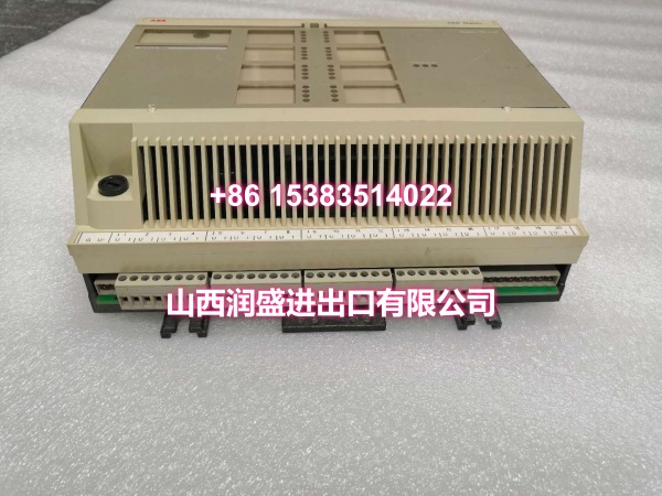
The ABB DSDX452 is a digital input/output combo module designed for ABB’s Advant Master and S100 distributed control systems. Unlike standard single-function I/O modules, the DSDX452 consolidates both digital input and digital output channels into a single unit, providing a space-efficient solution for applications that require mixed I/O in a compact footprint.
In industrial automation environments where rack space is at a premium, the DSDX452’s combo architecture delivers significant installation advantages. By combining input and output functionality in one module, it reduces the number of slots required in the I/O rack, simplifies cable routing, and lowers overall system cost compared to deploying separate DI and DO modules for small-scale I/O requirements.
The module accepts 24VDC digital input signals from field devices such as push buttons, limit switches, proximity sensors, and status contacts, while simultaneously providing 24VDC digital output channels for driving relays, contactors, solenoid valves, indicator lights, and alarm systems. Each channel features optical isolation between the field circuits and the backplane, protecting the control system from electrical noise, ground loops, and voltage transients.
Per-channel LED indicators provide immediate visual feedback on both input and output status, enabling rapid fault identification during commissioning and troubleshooting. The module’s comprehensive self-diagnostics continuously monitor channel health and report any detected faults to the operator station through alarm messages, minimizing mean time to repair.
As an “intelligent” S100 I/O module, the DSDX452 performs signal processing and data handling onboard rather than relying on the main controller’s CPU. This distributed processing architecture improves overall system real-time performance and reliability while maintaining processing capacity as the system scales.
For engineers maintaining legacy Advant Master or S100 installations, the DSDX452 is a direct drop-in replacement for failed or degraded digital I/O combo modules. Its standardized rack-mount form factor ensures compatibility with existing backplane configurations, avoiding costly mechanical rework or system redesign.
QA & Testing SOP
Every unit goes through a structured verification process before shipment:
- Visual Inspection: Check the module housing for cracks, corrosion on the backplane connector pins, and physical damage to the PCB. Verify that LED indicator lenses are intact and undamaged.
- Connector Pin Verification: Inspect the backplane connector pins for straightness, corrosion, or bending. Bent pins cause poor contact with the backplane, leading to intermittent channel failures or complete module communication loss.
- Input Channel Test: Using a 24VDC test source, apply voltage to each digital input channel and verify that the module correctly registers the input state. Confirm that the corresponding LED indicator illuminates appropriately for each active input.
- Output Channel Test: Command each digital output channel to change state from the DCS and verify that the output responds correctly. Measure the output voltage to confirm it meets 24VDC specifications under load.
- Isolation Verification: Where test infrastructure allows, verify that optical isolation between field circuits and the backplane is intact, ensuring no leakage between the module and the control system.
- Anti-Counterfeit & Packaging: Verify authenticity markings on the module body and PCB. Each unit is shipped in anti-static protective packaging with desiccant to prevent moisture absorption and connector oxidation during transit.
Installation Pitfalls & Guide
Installing or replacing a digital I/O combo module requires careful attention to both input and output wiring.
❗ Power-Down Before Installation: Always disconnect power to the rack or I/O section before removing or inserting the DSDX452 module. Digital I/O combo modules should be replaced with power off to prevent transient spikes from damaging the module or connected field devices.
❗ Wiring Verification: Before connecting field wiring to the new module, verify that each wire is correctly labeled and corresponds to the documented channel assignment. Miswired input channels can cause false readings, while miswired output channels can cause unintended equipment operation. Cross-reference the wiring diagram before making any connections.
❗ Input vs. Output Terminal Identification: The DSDX452 has separate terminals for digital inputs and digital outputs. Ensure that input field wiring is connected to the input terminals and output field wiring is connected to the output terminals. Reversing these connections can damage the module or connected devices.
❗ Load Current Verification for Outputs: Verify that the connected field devices do not exceed the module’s per-channel and total output current ratings. Overloading digital outputs can cause output stage failure or thermal damage.
❗ Shielded Cable Grounding: For field wiring runs exceeding 30 meters or passing through electrically noisy environments, use shielded cables with the shield grounded at the control cabinet end only. Grounding at both ends creates ground loops that can introduce noise into the input signals.
4-Step Replacement Guide:
- Pre-install: Document the existing channel assignments and wiring configuration for both input and output channels. Back up the DCS project. Verify the replacement module’s model (DSDX452) matches the original. Prepare anti-static protection and tools.
- Removal: Disconnect power to the I/O rack. Wear an anti-static wrist strap. Disconnect all field wiring from the terminal block and label each wire with its channel number and type (input or output). Loosen the module retention screws. Gently pull the module straight out of the backplane slot. Inspect the backplane connector for damage.
- Install: Align the new DSDX452’s connector with the backplane slot. Push firmly and evenly until fully seated. Tighten retention screws. Reconnect field wiring to the correct terminals according to the documented channel assignments, ensuring input wiring goes to input terminals and output wiring goes to output terminals. Verify that all connections are secure and properly torqued.
- Power-on Test: Apply power to the rack. Verify that the module’s status LED indicates normal operation. Enter the DCS diagnostic screen and confirm that all channels are recognized with no fault codes. Test each input channel by activating the connected field device and verifying the DCS reads the correct state. Test each output channel by commanding an output state change from the DCS and verifying the corresponding field device responds correctly. Monitor for several minutes to confirm stable operation.
Technical FAQ
1. What’s the advantage of using a combo I/O module like the DSDX452 versus separate DI and DO modules? The primary advantage is rack space savings. A combo module consolidates both input and output channels into a single slot, which is particularly valuable in space-constrained installations or when expanding an existing system with limited available slots. It also simplifies wiring by grouping related I/O in one location and can reduce overall system cost compared to purchasing separate DI and DO modules for small-scale I/O requirements.
2. Can the DSDX452 be used with ABB’s newer AC 800M or 800xA systems? The DSDX452 is designed for ABB’s Advant Master and S100 series systems. It is not directly compatible with newer platforms like AC 800M or 800xA, which use different backplane architectures and I/O module form factors (such as the S800 I/O system). If you’re migrating to a newer system, you’ll need to use the corresponding digital I/O modules designed for that platform.
3. What does “comprehensive self-diagnostics” mean for the DSDX452? The DSDX452 continuously monitors the health of each input and output channel. For input channels, it can detect open circuits and short circuits. For output channels, it detects overcurrent, short circuits, and output stage failures. Any detected faults are reported via per-channel LED indicators on the module front panel and communicated to the operator station through alarm messages. Faulty outputs can be automatically deactivated or driven to a predefined safe state to prevent unintended equipment operation.
4. Can the DSDX452 be configured in a redundant configuration? Some ABB S100 I/O modules can be configured in transparent dual-redundant configurations to improve system availability. Verify with your system configuration documentation whether the DSDX452 supports redundant operation in your specific Advant Master or S100 installation.
5. What’s the difference between New Surplus and Refurbished for digital I/O combo modules? We supply this unit as New Original (New Surplus)—unused, original factory stock. This comes with a standard 12-month warranty. Refurbished digital I/O combo modules carry risks including degraded input circuitry from prior overvoltage events, weakened output stages from previous overload conditions, and latent channel failures that may only manifest under specific load conditions. For a module that handles both critical input monitoring and output control, new surplus is the safer choice.