Product Core Brief
- Model: UFC760BE42
- Full OEM Part Code: 3BHE004573R0042
- Brand: ABB
- Series: UFC760 AC 800PEC dedicated power electronics control family
- Core Function: Execute high-speed real-time control algorithms for generator excitation systems (UNITROL 6000) and ACS6000 medium voltage drives; handle grid synchronization, voltage regulation, motor vector control, and high-frequency power conversion loop calculation via fiber and Ethernet communication interfaces.
- Product Type: Single-slot hot-swappable power electronics dedicated main processing CPU board (not standard AC800M process controller)
- Key Specs: Dual redundant 10/100M Ethernet ports | Isolated fiber optic Tx/RX high-speed drive bus | RS485 Modbus RTU multi-drop | Full G3 conformal coated PCB | Hot-swap certified for UNITROL/ACS6000 subracks ⚠️ EOL — limited surplus stock remaining
Product Introduction
The ABB 3BHE004573R0042 is a specialized real-time controller built exclusively for ABB power electronics platforms, including UNITROL 6000 generator excitation cabinets and ACS6000 medium voltage variable frequency drives. It differs fundamentally from the AC800M process CPU variants (UFC760BE43 / UFC760BE1142) — those are for general plant process control, while this model is engineered for microsecond-level power conversion and excitation control loops with fiber-optic high-speed drive communication.It cannot be used for standard S800 I/O process racks and requires matching UNITROL/ACS6000 dedicated subrack backplanes. OEM field logging records a 57,000 hour MTBF under steady 50 °C power cabinet runtime, optimized for high-vibration generator and drive room environments.
Key Technical Specifications
| Parameter | Value |
|---|---|
| Compatible Hardware | UNITROL 6000 excitation subracks, ACS6000 medium voltage drive cabinets; incompatible with standard AC800M System800xA S800 I/O racks |
| Official Full Part Number | 3BHE004573R0042 (short designation ) |
| Subrack Operating Supply | Mixed 5 VDC logic + ±15 VDC analog feed via dedicated backplane; total 430 mA typical steady-state draw |
| Communication Interfaces | Dual redundant 10/100M RJ45 Ethernet TCP/IP; isolated fiber optic Tx/RX high-speed drive control bus; isolated RS485 Modbus RTU multi-drop for auxiliary monitoring |
| PCB Environmental Protection | Full G3 conformal coating, anti-corrosion for coastal power plant, oil & gas drive cabinet atmospheres |
| Hot Swap Compliance | ABB power electronics certified hot-swap; fiber drive bus maintains synchronization during card replacement |
| Onboard Diagnostics | Continuous RAM/ROM self-test, fiber link loss alarm, dual Ethernet link fault detection, backplane undervoltage watchdog reset, excitation/drive overcurrent pre-alarm |
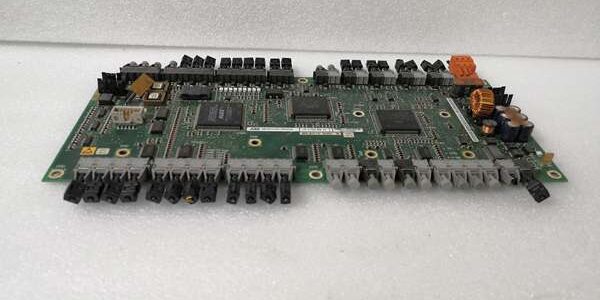
| Mechanical Form Factor | Single-width dedicated power electronics subrack slot, long PCB layout with terminal block marshalling |
| Mechanical Dimensions | 233 mm L × 160 mm W × 40 mm D |
| Net Unit Weight | 0.88 kg |
| Continuous Operating Ambient Temp | -5 °C to +70 °C full rated high-speed control performance; linear derate above 65 °C |
| Storage Temperature Range | -40 °C to +85 °C, 5–95 % RH non-condensing |
| Integrated Protection Circuits | Backplane reverse polarity lockout, Ethernet/fiber port ESD surge clamping, hardware watchdog automatic fault recovery, analog signal short-circuit limiting |
| Certifications | UL, CE, RoHS, EN61000 Class A industrial EMC filtering, power generation excitation system compliance |
Quality Control Process (Engineer’s Perspective)
- Incoming Verification: Cross-reference serial numbers against ABB OEM UNITROL/ trace databases; inspect conformal coating for chipping, gold subrack edge connectors for oxidation, fiber optic transceivers for dust contamination, terminal block screw threads for stripping. Photograph the full PCB pinout for excitation cabinet wiring reference.
- Live Functional Test: Seat the unit into a populated UNITROL 6000 test subrack paired with simulated generator PT/CT sensing circuits and fiber drive bus load simulators; run a continuous 24-hour cyclic voltage regulation and grid sync test with simulated generator load transients. Log subrack supply voltage stability with a Fluke 115 digital multimeter for the full test duration.
- Electrical Parameter Test: Perform a 1000 V Megger insulation resistance test between all fiber, Ethernet, analog sensing circuits and PCB chassis ground; pass threshold set at >10 MΩ. Verify dual Ethernet automatic failover triggers within 10 ms window when primary network cable is disconnected, fiber link maintains stable high-speed drive communication.
- Firmware Verification: Read and record factory AC 800PEC power control firmware revision via ABB UNITROL Service Tool software; document default Modbus RTU baud rate, fiber bus timing and excitation PID register settings for generator site commissioning reference.
- Final QC & Packaging: Wipe gold edge connectors and fiber transceiver windows to remove oxidation and dust; seal the unit inside an anti-static foam bag, affix a dated QC Pass label listing all completed communication, self-test, insulation and excitation regulation test metrics before rigid shock-resistant carton packing.
Replacement Pitfall Guide
❗ ❗ Partial Subrack Slot Insertion Risk: Uneven card seating creates high-resistance edge contact points that distort generator PT/CT analog sensing signals and cause excitation voltage hunting during grid load transients. Push the card fully into the dedicated power electronics slot and engage front locking latches flush against the subrack faceplate.❗ Fiber / Ethernet Cable Shield Ground Misconfiguration Risk: Unshielded CAT5e trunk wiring and unfiltered fiber routing parallel to high-current generator excitation cabling inject severe EMI noise that corrupts high-speed drive bus data. Use factory shielded Ethernet assemblies and cleaned fiber patch cords; terminate cable shield ground at only the main excitation cabinet terminal block end.❗ ❗ Uncontrolled ESD Damage Risk: Dry generator excitation room air builds static charge rapidly. Touch a grounded anti-static mat for three full seconds before handling gold edge connectors and fiber transceiver ports; ungrounded contact destroys low-tolerance fiber and analog power sensing ASICs.Keep these in mind and you’ll cut 90% of rework time.