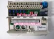
Product Core Brief
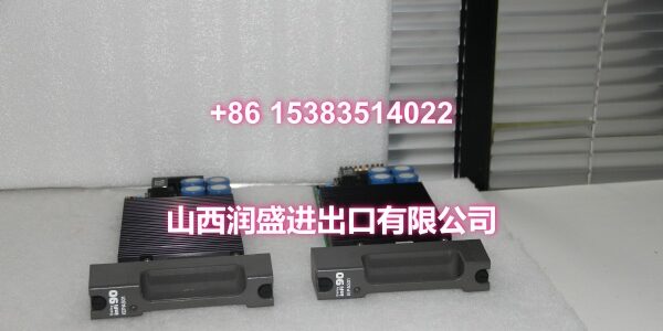
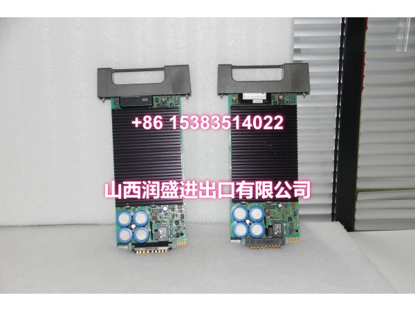
- Model: IMSED01
- Brand: ABB
- Series: Bailey Infi 90 / Symphony Harmony
- Core Function: Sequence-of-Events (SOE) digital input sub-module that captures high-speed, time-stamped discrete state changes for post-trip analysis and event reconstruction.
- Product Type: SOE digital input sub-module
- Key Specs: High-resolution time-stamping | Discrete input channels | Infi 90/Harmony sub-module
- Condition: New Original / New Surplus (subject to available stock)
Key Technical Specifications
| Parameter | Detail |
|---|---|
| Product Type | Sequence-of-Events (SOE) input sub-module |
| Compatible System | ABB Bailey Infi 90 / Symphony Harmony |
| Controller Compatibility | MFP controller modules (e.g., IMMFP series) |
| Input Type | Discrete / digital status inputs |
| Time-Stamping | High-resolution event time-stamping for SOE analysis |
| Primary Use | Trip sequence recording, relay/breaker event logging, fault reconstruction |
| Mounting | Harmony rack / MMU backplane sub-module slot |
| Typical Applications | Power generation trip logs, turbine protection events, breaker/relay sequencing |
| Packaging | Anti-static, industrial shipping pack |
| Availability | In-stock surplus / OEM replacement |
Note: Detailed channel count, input voltage rating, and time-stamp resolution should be confirmed against the module label or ABB documentation before commissioning, as published datasheet details for this legacy part are limited.
Product Introduction (No Fluff)
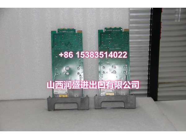
The ABB IMSED01 is a Sequence-of-Events (SOE) input sub-module for Bailey Infi 90 and Symphony Harmony systems. It records discrete field state changes — breaker trips, relay operations,
protection interlocks — with precise time stamps so engineers can reconstruct exactly what happened and in what order during a fault.
SOE modules matter most in power generation and critical process plants where milliseconds determine root cause. Unlike a standard digital input that simply reports “on” or “off,” the IMSED01 captures the sequence of events with enough resolution to separate near-simultaneous trips and identify the initiating event.
QA & Testing SOP (Dynamic & Transparent)
SOE modules are judged by timing accuracy, not just contact detection.
- Incoming inspection: Verify model marking, hardware revision, connector condition, and backplane pins. Check for corrosion, bent pins, or prior repair signs.
- Anti-counterfeit check: Inspect PCB finish, label formatting, serial consistency, and connector quality against known OEM characteristics.
- Power-up and self-test: Seat the module in a compatible Harmony test rack with an MFP controller. Confirm normal LED behavior and module initialization.
- Channel response test: Apply discrete input transitions and verify controller readback for each channel. Confirm clean state transitions without chatter or false triggers.
- Time-stamp verification: Where test fixtures allow, inject simultaneous or near-simultaneous transitions on multiple channels and verify that time-stamped event records are captured in the correct sequence.
All units are packed in anti-static bags with connector protection. Because full SOE time-stamp validation requires a compatible MFP and configuration, we can document basic channel response and power-up behavior as a minimum. If your site requires documented SOE timing verification, request it before ordering.
Installation Pitfalls & Guide (Engineer to Engineer)
This is not a standard DI card. SOE accuracy depends on wiring discipline and clock synchronization.
❗ Do not substitute a standard DI module for SOE. The IMSED01 is purpose-built for time-stamped event capture. A regular digital input module will not provide the resolution needed for trip sequence analysis.
❗ Verify controller clock synchronization. SOE time stamps are only meaningful if the MFP controller clock is synchronized with the rest of the system. A drifting clock corrupts event reconstruction.
❗ Use shielded wiring for SOE inputs. Noise on discrete input wiring can create phantom transitions that appear as false events in the SOE log. Keep SOE wiring separated from power cables.
❗ Confirm the sub-module slot assignment. The MFP must be configured to recognize the IMSED01 in its assigned sub-module slot. An incorrect slot map prevents the controller from reading SOE data.
Replacement steps
- Pre-install: Document existing channel assignments, SOE block addresses, and time-stamp configuration. Export the current SOE log if accessible.
- Removal: Place affected protection logic in a safe state per site procedure. Remove the sub-module carefully from the rack.
- Install: Inspect backplane contacts, seat the module fully, and verify the MFP recognizes the sub-module.
- Commissioning test: Force known discrete transitions, verify controller readback, and confirm time-stamped events appear correctly in the SOE log before restoring protection logic.
Technical FAQ
Is the IMSED01 still available? Yes, as new surplus and OEM replacement stock. This is a legacy module, so availability varies by batch. Confirm current quantity before scheduling a maintenance window.
How is the IMSED01 different from a standard digital input like the IMDSI14? The IMDSI14 is a general-purpose 48 VDC digital input module. The IMSED01 is an SOE-specific input module designed to capture time-stamped events with higher resolution for post-trip analysis. They are not interchangeable without reconfiguration.
Can it replace the IMSET01? Both are SOE modules in the Infi 90 family, but they may differ in channel count, input voltage, or time-stamp resolution. Verify the exact specifications against your existing configuration before substituting one for the other.
What is the warranty? Surplus units typically carry 30–90 days depending on condition. New original stock may qualify for longer coverage. The exact term is stated on the quote.
Can you provide a test report? Yes, on request. We can document power-up status, channel response checks, and visual inspection notes. Full SOE time-stamp validation requires a compatible test rack and MFP controller.