

Quick Sizing & Sourcing Snapshot
- Manufacturer: Schneider Electric / Legacy Invensys Foxboro (USA origin)
- Part Number: FBM12; matching field terminal assembly = P0904BC / P0904BD dedicated RTD termination base
- System Platform: Foxboro Classic I/A Series + Foxboro Evo DCS, compatible with CP30, CP60, FCP280 rack controllers
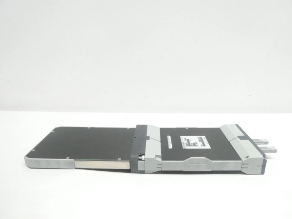
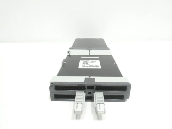
- Hardware Type: Single-slot baseplate mounted 8-point isolated RTD analog input FBM card
- Architectural Role: Scans 2/3-wire RTD field temperature sensors, converts resistance values to engineering units locally, transmits scaled process data to rack master CPU over redundant Nodebus HDLC backplane bus
- Key Specifications: 8 galvanically isolated RTD channels, supports Pt100/Cu50 standard sensors, software configurable wire type selection per channel
P0400YD
System Architecture & Operational Principle
sits on the field I/O tier of the Purdue automation model, populated directly onto standard I/A Series HDLC baseplate alongside discrete FBM206/FBM217 DI modules and host rack controllers. Upstream, it receives scan timing, RTD type selection, cold-junction offset parameters and alarm thresholds from CP/FCP controllers via dual redundant 2Mbps Nodebus backplane during DCS control builder download cycles.
Downstream, field RTD sensor wiring lands on paired P0904XX terminal assemblies; module’s onboard precision constant-current source injects fixed excitation into each RTD leg to read proportional resistance changes tied to process temperature. Onboard sigma-delta ADC converts raw resistance readings into digital values, applies programmed linearization for Pt100 curves before buffering data. Redundant Nodebus design prevents single cable failure from knocking out full module communication, a critical advantage for continuous temperature monitoring on refining and power unit critical loops.
Core Technical Specifications
- Physical Interface: Gold-finger rear baseplane connector; front snap lock for direct P0904BC terminal docking
- Signal Type: 2-wire / 3-wire Pt100, Cu50 RTD resistance-based temperature input
- Channel Density: 8 independent isolated RTD input channels per single rack slot
- Communication Bus: Dual redundant 2Mbps HDLC Nodebus backplane
- Environmental Tolerance: -20°C ~ +60°C operational; -40°C ~ +85°C storage; ISA G3 corrosive gas environment rated
- Power Draw: Nominal 2.8W sourced entirely from baseplate 24VDC SELV supply
- Isolation Rating: 1500VAC channel-to-channel and field-to-backplane opto-galvanic isolation
- Excitation Current: Fixed 0.5mA constant per channel precision drive for RTD measurement
- Hot-Swap Rating: Hot plug permitted only on redundant Nodebus baseplate; simplex racks require software channel disable pre-replacement
- Accuracy Rating: ±0.1% full span after factory calibration, ≤0.01% monthly long-term drift
Customer Value & Operational Benefits
Cut Unplanned Process Trips From Bad RTD WiringPer-channel electrical isolation confines shorted field sensor cabling to individual temperature points instead of corrupting adjacent loop readings; plant teams eliminate false high/low temperature alarms triggered by cross-wire leakage common on non-isolated multi-RTD cards, lowering unplanned process shutdown frequency.
Shrink Calibration Man-Hour OverheadSoftware-driven per-channel wire type switching removes need for field terminal jumper rewiring when swapping between 2-wire and 3-wire RTD devices; maintenance crews cut loop calibration time by nearly 40% during plant turnaround upgrades.
Optimize Cabinet Space During I/O Expansion8 high-precision temperature inputs per single slot reduces required rack real estate vs older 4-point legacy FBM RTD modules, lowering auxiliary cabinet procurement spend for new unit instrumentation rollouts.
Field Engineer’s Notes (From the Trenches)
I’ve repaired dozens of drifting units across gas-fired power and chemical plant sites caused by two avoidable field errors. First, technicians frequently reuse leftover 4-20mA analog cable for 3-wire RTD runs; mismatched conductor resistance skews cold-compensation readings over seasonal ambient swings, creating slow temperature drift that takes weeks to isolate. Second, installing terminal shield grounds at both instrument junction box and DCS cabinet creates ground loop induced noise that bounces temperature values ±2~3°C randomly. Always run dedicated twisted-pair RTD-grade cable, limit shielding single-point grounding exclusively at DCS terminal bar, and avoid bundling RTD wiring alongside 480V motor power cables in shared trays. Never force-fit non-P0904 series generic terminals onto front header; pin misalignment can permanently damage onboard excitation drive circuitry.
Real-World Applications
- Natural Gas Processing Plant Feed Preheater Rack: with P0904BD terminals monitors shell and tube preheater inlet/outlet Pt100 RTD sensors; collected temperature data feeds furnace feedstock trim control logic hosted on FCP280 controller to regulate burner fuel valve positioning and prevent overheating tube rupture events.
- Coal Power Plant Boiler Waterwall Temperature Monitoring: Module terminates hundreds of boiler tube surface 3-wire Pt100 RTDs distributed across furnace waterwall panels; DCS uses sampled readings to flag localized tube overheating and initiate boiler load reduction before tube fatigue failure and forced unit outage.
High-Frequency Troubleshooting FAQ
A: Basic Nodebus communication works but mismatched firmware causes sporadic single-channel dropout and incorrect RTD linearization; always match FBM firmware revision to controller runtime version listed in Foxboro official compatibility matrix before rack energization.
Q: Why do individual channels show gradual slow temperature creep with no physical RTD sensor fault found?A: Nearly always tied to improper dual-ended cable shielding or degraded field terminal crimp resistance; re-terminate all RTD wiring at cabinet terminals and relocate shared signal cabling away from high-voltage power feed trays to resolve slow drift.
A: Not recommended. Live removal disrupts active Nodebus scan cycle and can glitch connected temperature control loops; always disable module scan inside Foxboro Control Builder software before powering down and swapping hardware.
Commercial Availability & Pricing
Please note: The listed price is not the actual final price. It is for reference only and is subject to appropriate negotiation based on current market conditions, quantity, and availability.


