Quick Sizing & Sourcing Snapshot
- Manufacturer: GE (General Electric)
- Part Number: IS200EACFG1B
- System Platform: EX2100 / EX2100e Excitation Control (Mark VI/VIe)
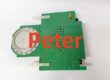
- Hardware Type: Exciter AC Feedback Board (EACF)
- Architectural Role: Conditions and fans out Generator PPT (Voltage) and Air Core CT (Current) signals to the M1, M2, and C controllers via DB9 links.
- Key Specifications: 480V RMS Input Rating (G1), 3x DB9 Outputs, 2 Flux Coil Terminals.
System Architecture & Operational Principle
The is a passive signal-conditioning hub located in the Exciter Auxiliary Cabinet. It is the “G1” variant in the EACF family, designed for systems with lower PPT secondary voltages (rated 480V RMS nominal, +20% transient).
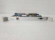
Physically, it mounts to the cabinet framework (chassis mount). Upstream, it receives raw 3-phase AC from Generator Potential Transformers (PPTs) and signals from Air Core Current Transformers (CTs) at its screw terminals (TB1-TB3 for PPT, TB4 for CT). The board uses internal step-down transformers (T2, T3) to isolate and scale these signals. Downstream, it has no active processing; it “fans out” the conditioned signals via three 9-pin D-Sub (DB9) connectors (J504 to M1, J409 to M2, J514 to C). This allows the three TMR (Triple Modular Redundant) controllers on the EBKP backplane to independently vote on AC feedback for the AVR (Automatic Voltage Regulator) loop. It operates at Level 1/2, providing the sensory interface required to regulate generator terminal voltage.
Core Technical Specifications
- Voltage Rating (G1): 480V RMS (Nominal +20% Transient Tolerance)
- Current Inputs: Air Core CT (0 to 0.8V RMS), 2 Terminals (TB4)
- Voltage Inputs: 3-Phase PPT (L1, L2, L3), Terminals TB1, TB2, TB3
- Output Interfaces: 3x DB9 (D-Sub) -> J504 (M1), J409 (M2), J514 (C)
- Transformers: T2, T3 (Active Signal Conditioning), T1/T4 (Omitted/Spare)
- Test Points: TP1-TP4 (Phase-to-Phase: AB, BC, CA @ Scaled ~1.6V)
- Power: Passive (No Active Consumption; Signal Sourced from PT/CT)
- Indicators: None (Blind Board; Diagnostics via Controller/EBKP)
- Coating: Conformal Coated (Revision B)
- Mounting: Chassis Mount (Exciter Aux Cabinet Framework)
- Max Cable Length: Up to 90m (300ft) to EBKP
Customer Value & Operational Benefits
Voltage Rating Specificity (G1)
The “G1” (480V) rating is critical for smaller gen-sets or units with lower PPT ratios. Using a G2 (1000V) or G3 (1400V) here works electrically at low volts, but the transformer turns ratio is optimized for higher voltages. The G1 ensures the best signal-to-noise ratio (SNR) when your PPT secondaries are in the 70-120V AC range, preventing AVR “hunting” (VAR oscillation) caused by under-scaled signals.
TMR Signal Isolation
By fanning out via dedicated DB9s to M1, M2, and C, the board ensures galvanic separation of the redundant paths at the sensor level. If a fault (e.g., lightning surge) spikes the PPT wiring and cooks the T2 transformer on thisboard, it won’t propagate to the M1 processor’s ADC. The M2 and C paths remain viable for the 2oo3 vote.
Centralized Calibration Access
The TP1-TP4 test points provide scaled AC voltage (approx 1.6V AC for 120V PT secondary). You can verify PPT phasing and scaling with a DMM right at the board while synchronized at 100% load, without probing live high-voltage bushings or pulling EBKP cards. This speeds up AVR tuning and “Volts Mismatch” diagnostics.
Field Engineer’s Notes (From the Trenches)
This board is “Blind”—zero LEDs. When the AVR goes unstable (VAR hunting), don’t just swap the M1 processor. Grab a Fluke 115.
Check TP1 to TP2 (Phase A-B). You should see the scaled PPT voltage (~1.6V AC for 120V secondary). If TP1-2 reads 0V but your PPT secondary panel reads 120V AC, the T2 transformer on the EACFG1B is open (likely cooked by a past surge on the grid).
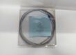
Shield Drains: The DB9 cables (J504 etc.) have shield drains. The grounding screw is on the EACF metal chassis, within 3 inches of TB1. Land the shield drain there, not at a distant cabinet ground bar. Running the shield 10 feet to a remote bus creates a ground loop; 60Hz hum injects into your AC feedback, causing the generator to hunt under load swings.
Torque TB1-TB3. These are PPT inputs. A loose L2 connection causes “Phase Imbalance” or “Volts Loss” in the TMR vote. Use a 0.5-0.6 Nm driver; exciter fan vibration loosens standard screws over a year.
Real-World Applications
- 50MW Gas Turbine Generator (13.8kV:120V PPT): The EACFG1B handles PPT secondaries (~120V AC nominal). It scales and isolates these for the M1, M2, C controllers managing the static exciter’s AVR loop. The 480V rating is perfect for this PPT ratio.
- Industrial Steam Turbine (4160V Drive): Terminating Air Core CT signals (representing DC Field Current as AC). The G1 rating handles electrical noise from the 6-pulse thyristor bridge adequately for mid-size units, preventing spurious “Field Over Current” trips.
High-Frequency Troubleshooting FAQ
Q: ToolboxST shows “Voltage Feedback Loss” or “PPT Signal Invalid” on M1 only. EACFG1B looks fine. Where’s the fault?
A: The EACF fans out to all three. If only M1 complains, the issue is the DB9 Cable (J504) or the M1’s EBKP receiver, not the EACF board itself. Wiggle the thumbscrews on J504; vibration loosens these. If tight, ohm the 9-pin cable (Pin 2-3, 4-5, 6-7 for phases). A broken pin 3 kills the A-B voltage signal to M1.
A: Electrically functional, but suboptimal for control quality. Pinouts are identical, and it will “work” at 120V nominal. However, the G2’s T2/T3 transformers are wound for higher voltages. At 120V input, the output to the DB9 (scaled signal) is proportionally lower, reducing your signal resolution at the ADC. This can make the AVR loop “jittery” or slow to respond to small grid disturbances. Use G1 for G1-rated systems.
Q: TP1-TP2 reads 0V AC, but PPT secondaries are live at the terminal block. Is the board trash?
A: Likely, yes. Check for a blown fuse (if equipped on specific sub-revs) near T2. If the fuse is good, the T2 transformer winding is open (cooked from a past surge). The EACF is passive; if input power is verified at TB1/TB2 but test points are dead, the board took the hit. Verify no shorts on the PPT field wiring (L1-L2 short) before installing the replacement, or you’ll blow the new T2 in seconds.
Please note: The listed price is not the actual final price. It is for reference only and is subject to appropriate negotiation based on current market conditions, quantity, and availability.