Product Core Brief
- Model: 176449-01 (3500/40M)
- Brand: Bently Nevada
- Series: 3500 Machinery Protection System
- Core Function: Monitors shaft relative vibration, axial displacement, and differential expansion using eddy-current proximity probes.
- Product Type: 4-Channel Proximitor Displacement Monitor
- Key Specs: 4-Channel | Radial Vibration / Axial Displacement / Eccentricity / Differential Expansion | API 670 Compliant
- Condition: New Surplus / Original OEM
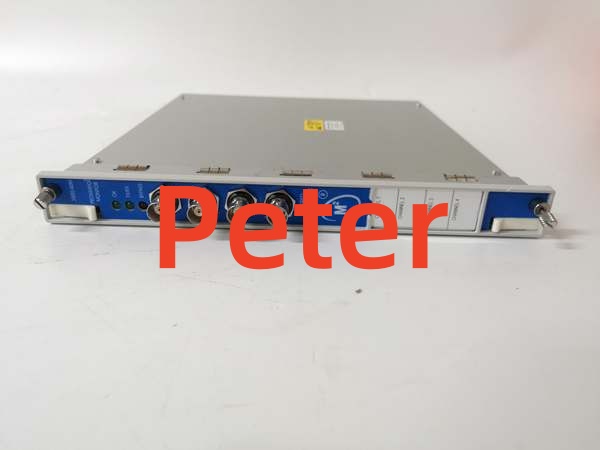
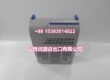
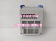
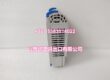
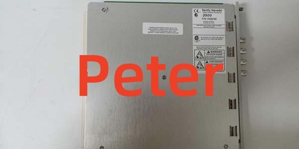
BENTLY 3500/40M 176449-01
Key Technical Specifications
- Manufacturer: Bently Nevada
- Part Number: 176449-01
- Product Category: Proximitor Displacement Monitor Module
- System Architecture: Bently Nevada 3500 Rack
- Channel Count: 4 Independent Channels (Configurable in pairs)
- Input Type: Eddy-Current Proximity Probe
- Measured Parameters: Radial Vibration, Axial Displacement, Eccentricity, Differential Expansion
- Sensitivity: 3.94 mV/µm (100 mV/mil) or 7.87 mV/µm (200 mV/mil)
- Operating Temp Range: -30°C to +65°C
- Compliance: API 670 / CE / CSA
Product Introduction (No Fluff)
This 176449-01 serves as the primary vibration and position monitor within a Bently Nevada 3500 rack, continuously tracking shaft relative motion for critical rotating equipment like turbines and compressors. It processes raw signals from eddy-current proximity probes to detect imbalance, misalignment, and bearing wear, generating vital alarm and trip signals.
Sourcing this exact OEM replacement part prevents catastrophic machinery damage when monitor modules fail or drift out of calibration. Keeping verified new surplus stock on hand drastically reduces unplanned downtime during critical backplane failures or when expanding protection coverage.
QA & Testing SOP (Dynamic & Transparent)
Vibration monitors demand absolute signal fidelity. Every 176449-01 undergoes an inbound anti-counterfeit inspection, verifying PCB silkscreen, component lot codes, and Bently Nevada factory labels. Next, the module is mounted on a dedicated 3500 test rack to validate backplane communication and channel initialization. We inject simulated proximity probe signals to verify the module accurately calculates direct vibration amplitude and gap voltage across all four channels. Finally, a 4-hour continuous burn-in under nominal backplane power catches marginal A/D converters before they reach your panel. All units ship in dual-layer ESD shielding with a printed QA test report.
Installation Pitfalls & Guide (Engineer to Engineer)
❗ Channel Pairing Logic: The 3500/40M channels are configured in pairs. Channels 1 & 2 can be set for one function (e.g., Radial Vibration), while channels 3 & 4 perform another (e.g., Axial Displacement). Misconfiguring this in the 3500 Configuration Software will result in invalid readings or module faults.
❗ Shielded Cable Grounding: Proximity probe cables must use proper shielded wiring to prevent EMI from corrupting the micro-volt vibration signals. Ground the shield at the monitor module terminal block only. Grounding at both ends creates a ground loop that introduces 50/60 Hz hum into your vibration readings.
❗ Sensor Calibration Mismatch: The 176449-01 expects a specific transducer sensitivity (e.g., 7.87 mV/mil or 200 mV/mm). If you are replacing a module after a field failure, verify that the new module’s configuration matches the installed proximity probe system’s calibration curve. A mismatch will cause significant scaling errors.
Replacement Protocol:
- Pre-Install: Lock out the 3500 rack power. Verify 0 VDC at the backplane. Ground yourself properly.
- Removal: Release the front panel retaining screws. Extract the failed module straight out. Inspect the backplane connector for bent pins.
- Install: Align the 176449-01 with the guides. Seat it firmly and secure the faceplate screws. Reconnect the BNC coaxial sensor cables.
- Power-on Test: Restore rack power. Use the 3500 Configuration Software to verify the module is recognized. Check the front panel OK LEDs and validate live vibration readings against a handheld meter.
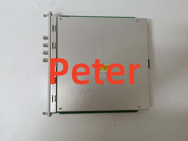
BENTLY 3500/40M 176449-01
Technical FAQ
Is this an exact drop-in replacement for my older 3500/40M module?
Yes, the 176449-01 maintains complete backward compatibility with existing 3500 racks and configurations. It offers the same 4-channel displacement monitoring and integrates seamlessly with the 3500 Configuration Software. You can swap it directly into an older slot without reconfiguring the entire rack.
Why is this listed as “New Surplus” instead of factory-new?
This is genuine Bently Nevada stock that was never deployed in a power plant or refinery. It has been stored in climate-controlled inventory rather than exposed to harsh industrial environments. You receive the exact same MTBF and lifespan as a factory-fresh unit, typically at a significantly lower cost and without the 16-week lead time.
Can I hot-swap this proximity monitor while the 3500 rack is live?
No. The 3500 backplane does not support hot-swapping the proximity monitor module. Removing it under power will cause an immediate loss of vibration monitoring for the connected channels, potentially disabling critical machinery protection. Always schedule this replacement during a planned outage or shutdown window.
What is the warranty coverage on this part?
We provide a standard 12-month functional warranty. If the module fails under normal operating conditions within that window, we replace it. Our QA testing proves the module processed vibration signals accurately before it left our bench, so we stand behind our inventory.
My 3500 system is aging. Should I replace this module or plan a full 3500 to Orbit 60 migration?
If this is an isolated failure, replacing the 176449-01 is the most cost-effective way to keep your machinery protection system compliant with API 670. However, if you are experiencing cascading backplane communication errors or multiple monitor failures, your entire rack may be nearing end-of-life. Use this replacement as a bridge to schedule a comprehensive migration during your next major turnaround.
Need me to pull up the 176449-01 BNC pinout for the proximity probe wiring or the channel pairing configuration guide? That usually comes up right before reconnecting the sensor cables.