")
Quick Sizing & Sourcing Snapshot
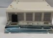
- Manufacturer: GE Fanuc (Emerson Machine Automation)
- Part Number: IC200ERM002
- System Platform: GE VersaMax PLC / I/O Stations (Compact & Micro)
- Hardware Type: Non-Isolated Expansion Receiver Module (ERM)
- Architectural Role: Acts as the head unit for a VersaMax expansion I/O rack, receiving the serial expansion bus from the CPU/NIU and distributing it to up to 8 I/O modules in that rack, while passing the bus to the next rack.
- Key Specifications: 7 Rack Max, 15m (50ft) Multi-Rack Cable, 26-pin D-Shell Ports, 5V Backplane.
System Architecture & Operational Principle
The sits at Purdue Level 1/2, occupying Slot 0 (Leftmost position) of a VersaMax expansion I/O rack (e.g., IC200CHS022). It is the gateway that allows you to step outside the main CPU rack and distribute I/O physically closer to the field devices.
Upstream, it connects to the IC200ETM001 (Expansion Transmitter) module in the CPU rack (or the previous expansion rack) via a 26-pin D-Shell cable (proprietary serial bus).
Internal Function, it regenerates the bus signals and powers the backplane logic. It does notisolate the expansion bus; it is Non-Isolated, meaning the 5V logic reference is common across all chained racks. This keeps cost down but requires a solid common ground strategy.
Downstream, it fans the bus out to the 8 I/O module slots in its own rack via the backplane. It also has a second 26-pin D-Shell port (Lower) used to daisy-chain the cable to the next in the subsequent rack (Rack ID 2, 3, etc.).
Configuration is set via a Rotary Switch (0-7) on the module face, defining the Rack ID. The CPU uses this ID to map the I/O addresses (e.g., %I0010xx refers to Rack 1). It supports 7 expansion racks total (IDs 1-7). In multi-rack setups, total cable length cannot exceed 15 meters (50 feet); in single-ended mode (one rack), keep it under 1 meter (3.3 ft).
Core Technical Specifications
- Expansion Capacity: 7 Racks (Max, IDs 1-7), 8 Modules per Rack
- Bus Interface: 2x 26-pin D-Shell (Female, Top In / Bottom Out/Daisy)
- Communication Rate: 2.765 Mbps or 5 Mbps (System Dependent)
- Backplane Power: 5V DC (Sourced from on-board Pwr Supply, e.g., IC200PWR001)
- Current Draw: 70 mA @ 5V DC (Module Only)
- Rack ID Config: Rotary Switch (0-7, 0=Disabled/Single-Ended)
- Cable Length: 15m Max (Multi-Rack), 1m Max (Single-Ended)
- Indicators: PWR (5V Present), SCAN (Green=Active/Amber=No Scan), EXP RX (Bus Activity)
- Isolation: Non-Isolated (Common 5V/Logic Ground across racks)
- Mounting: DIN Rail (35mm Standard)
- Operating Temp: 0°C to +60°C (Operational)
Customer Value & Operational Benefits
Distributed I/O Without Network Overhead
The ERM002 lets you put 8 I/O modules (e.g., 256 discrete points) right at the motor control center or valve yard, 50 feet from the CPU, using cheap 26-pin ribbon cable instead of running 40+ homerun wires. You avoid the cost of an Ethernet switch and IP addresses required for EtherNet/IP remote racks. For simple distributed skids (pump houses, bagging lines), this cuts material costs by 30% and simplifies the network architecture.
Simple Addressing (Rack ID Switch)
You don’t need a laptop to set the node address. The Rotary Switch (0-7) is idiot-proof. Arriving at a site with a replacement rack, you twist the switch to “2” to match the dead unit, land the 26-pin cables (Top from Rack 1, Bottom to Rack 3), and power up. The CPU sees it instantly. This reduces commissioning errors where a tech downloads the wrong “Node 3” config to a physical “Node 2” rack.
Compact Footprint (Slot 0 Design)
By integrating the receiver logic into a single-width module that mustgo in Slot 0, GE eliminated the need for a separate “Expansion Head” box or bulky interface card. The power supply (IC200PWR001) stacks directly on topof the ERM002 (via a male/female header), creating a 2-slot wide “Head” that leaves slots 1-8 for pure I/O. This maximizes density in shallow panels.