Product Core Brief
- Part Number: DS200IIBDG1A
- Brand: GE (GE Energy / GE Digital / GE Industrial Systems)
- Series: GE Speedtronic Mark V / DS200
- Core Function: IGBT gate driver (IIBD) board providing isolated gate drive, current/voltage/fault feedback, and internal power conversion for IGBT-based drive stages.
- Product Type: Mark V IGBT Gate Driver Board
- Key Specs: 6 optically isolated IGBT gate driver circuits | per-phase current, voltage, and fault feedback | internal isolated power | 9 red LEDs | ribbon cable connector | jumpers | legacy/obsolete product
- Condition: New Original / New Surplus
Product Introduction
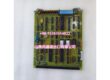
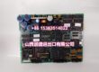
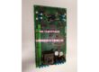
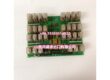
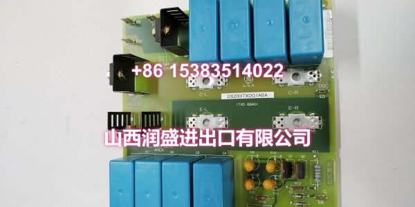
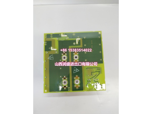
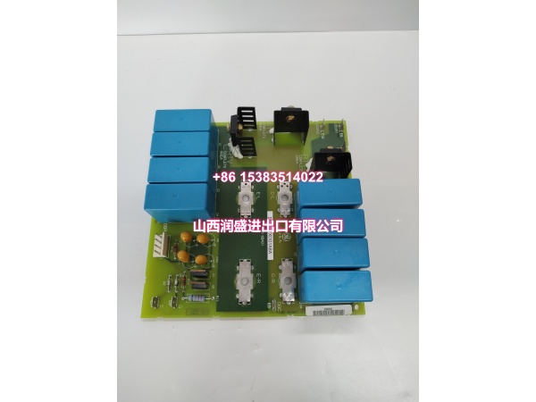
GE DS200IIBDG1A is an IGBT gate driver board for the GE Speedtronic Mark V control system family. The IIBD function group is used in drive-related applications where insulated-gate bipolar transistors must be driven, monitored, and protected.
The board includes six optically isolated IGBT gate driver circuits, with upper and lower IGBT drivers for each output phase. It also integrates current, voltage, and fault feedback circuits for each phase. An internal power section supplies the IGBT gate circuits and the shunt-feedback VCO, using isolated transformers for each output phase.
Nine red LEDs provide operational status and can be observed from inside the board cabinet when the system is energized. The board uses multiple connectors, including a 32-pin ribbon cable connector, and contains user-configurable jumpers as well as factory-set test jumpers. Because some public listings describe this part number as an analog I/O board, the exact application, connector map, and jumper settings should be confirmed from the physical board label and GE Mark V documentation before installation.
Key Technical Specifications
| Parameter | Value |
|---|---|
| Manufacturer | GE (GE Energy / GE Digital / GE Industrial Systems) |
| Part Number | |
| Product Type | IGBT Gate Driver (IIBD) Board |
| Series | GE Speedtronic Mark V / DS200 |
| Typical Application | IGBT gate drive, current/voltage/fault feedback, drive power stage |
| Gate Driver Circuits | 6 optically isolated IGBT gate drivers (upper + lower per phase) |
| Feedback | Per-phase current, voltage, and fault feedback |
| Internal Power | Isolated power for IGBT gate circuits and shunt-feedback VCO |
| Indicators | 9 red LEDs |
| Connectors | Multiple connectors including a 32-pin ribbon cable connector |
| Configuration | User jumpers + factory-set test jumpers |
| Status | Legacy / Obsolete |
Note: Public documentation confirms the IIBD IGBT driver function, six isolated gate drivers, feedback circuits, internal power, 9 LEDs, ribbon cable connector, and jumpers. The exact drive system assignment, connector pinout, LED fault map, and jumper configuration should be confirmed from the physical board label and GE Mark V manuals.
Quality Control Process (DYNAMIC GENERATION)
- Visual and label inspection. We check the part number, revision suffix, PCB surface, connectors, LEDs, jumpers, and mounting hardware for damage or corrosion.
- Connector and ribbon cable check. The 32-pin ribbon cable connector and other board connectors are verified for correct seating, pin continuity, and no short circuits.
- Jumper verification. User-configurable and factory-set jumpers are recorded and compared against the original board or system documentation.
- LED and feedback check. The 9 red LEDs and feedback circuitry are inspected for proper presence and condition.
- Final packaging. After passing inspection, the board is anti-static bagged and foam-packed for shipment.
Replacement Pitfall Guide (DYNAMIC GENERATION)
❗ Verify the exact board function. Some listings describe DS200IIBDG1A as an analog I/O board; confirm it is the IIBD IGBT driver board from the physical label before installation.
❗ Label all connectors before removal. Record connector identifiers and cable positions to prevent miswiring during replacement.
❗ Handle the ribbon cable carefully. The 32-pin ribbon cable connector has locking tabs; release both tabs before removal and avoid damaging individual conductors.
❗ Copy jumper settings from the original board. Incorrect jumper configuration can affect gate drive behavior or feedback scaling.
❗ Record LED status before removal. The 9 red LEDs provide operational/fault information; document them for troubleshooting.
❗ Observe high-voltage safety. The board is associated with IGBT power stages; disconnect drive power and use insulated test equipment when verifying signals.
❗ Handle as ESD-sensitive equipment. Always use anti-static wrist straps and handling procedures during removal, installation, and storage.
Keep these in mind and you’ll cut 90% of rework time.
Compatibility Matrix & Benchmarks
| Original Model | Replacement / Successor Model | Compatibility Level | Migration Notes |
|---|---|---|---|
| GE | GE | Direct | Same part number; verify jumpers, LED map, and connector layout. |
| GE | GE DS200IIBDG1 variants | Needs Adaptation | Same IIBD family; suffix differences may affect revision or configuration. |
| GE | GE 531X304IBDASG1 | Needs Adaptation | Different IGBT board family; not a direct drop-in replacement. |
| GE | Mark VIe / IS200/IS220 modules | Not Compatible | Different platform and architecture; not a direct replacement. |
Benchmark highlights
- GE Speedtronic Mark V IGBT gate driver (IIBD) board.
- Six optically isolated IGBT gate drivers for upper and lower devices per phase.
- Integrated current, voltage, and fault feedback per output phase.
- Internal isolated power for IGBT gate circuits and shunt-feedback VCO.
- 9 red LEDs for operational and fault indication.
- Multiple connectors including a 32-pin ribbon cable connector.
- User and factory-set jumpers for configuration.
- Legacy product; best suited for existing Mark V drive system maintenance and like-for-like replacement.