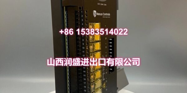
Product Core Brief
- Model: 369B1844G5004
- Brand: GE
- Series: GE DCS System I/O Module
- Core Function: Provides discrete relay output channels for GE DCS platforms to drive valves, contactors, alarms, and field actuators.
- Product Type: DCS Digital Output Module / Relay Output Card
- Key Specs: 16 relay output channels | 2 A per channel @ 250 VAC/30 VDC | ≤10 ms response time
- Condition: New Original / New Surplus
Key Technical Specifications
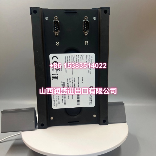
- Part Number: 369B1844G5004
- Module Type: Digital Output Module
- Output Type: Relay output
- Output Channels: 16 channels
- Load Rating: 2 A per channel at 250 VAC / 30 VDC
- Response Time: ≤10 ms
- Supply Voltage: Typically 24 VDC system supply
- Isolation: Channel/potential isolation supported
- Mounting: Standard DCS rack / DIN-rail compatible mounting
- Protection Class: IP20 (panel/cabinet mounted)
- Operating Temperature: -20°C to +60/70°C, depending on configuration
- Typical Applications: Valve control, motor start/stop commands, alarm outputs, interlock signaling
Product Introduction (No Fluff)
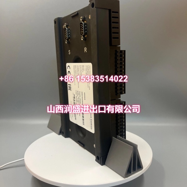
The GE 369B1844G5004 is a 16-channel digital output module used in GE DCS systems. It converts controller logic commands into discrete relay outputs for field devices such as solenoid valves, contactors, indicator lamps, and alarm circuits.
This card is most useful during DCS maintenance, retrofit, or spare-part replacement. Because output modules sit directly in the trip and control path, verifying channel count, relay type, and load rating before installation is critical.
QA & Testing SOP (Dynamic & Transparent)
For a relay output card, we focus on contact integrity, load capability, and backplane communication.
- Label and revision check: Confirm 369B1844G5004 on the module label. Record any firmware or hardware revision markings for traceability.
- Visual inspection: Check the backplane connector pins, terminal block, relay housing, and PCB for corrosion, burnt marks, or mechanical stress.
- Backplane communication test: Seat the module in a compatible GE DCS rack and verify that the controller recognizes the card without I/O faults.
- Channel-by-channel output test: Energize each relay output individually. Verify contact closure, LED indication, and correct channel mapping.
- Load and voltage check: Apply a rated resistive load where possible and measure contact voltage drop. Reject modules with sticking contacts, abnormal heating, or inconsistent switching.
- ESD-safe packaging: Ship in anti-static bags with foam support. Include part number, channel count, and test status on the label.
Installation Pitfalls & Guide (Engineer to Engineer)
❗ Do not exceed the 2 A per channel rating. Relay outputs can look robust on paper, but inductive loads such as solenoids and contactor coils can cause arcing and premature contact failure.
❗ Verify channel mapping before commissioning. A replacement card may be recognized by the rack, but incorrect addressing can energize the wrong field device.
❗ Check backplane pins carefully. Bent or oxidized pins are a common cause of intermittent I/O faults. Inspect before fully seating the module.
❗ Confirm supply voltage and polarity. Applying the wrong auxiliary voltage can damage the module or cause nuisance trips in the DCS rack.
Replacement steps:
- Pre-install: Back up DCS configuration, record channel assignments, and isolate field loads where possible.
- Removal: De-energize the rack or follow OEM hot-swap rules. Label wiring and remove the faulty card without forcing connectors.
- Install: Inspect pins, seat the new module firmly, and reconnect field wiring with correct polarity.
- Power-on test: Restore power, verify controller recognition, test each output channel, and confirm field device operation under controlled conditions.
Technical FAQ
Is this module compatible with my GE DCS system?
Compatibility depends on the specific GE DCS platform and rack configuration. 369B1844G5004 is described as a GE DCS digital output module, but you should verify it against your installed system documentation before ordering.
How many outputs does it provide?
It provides 16 relay output channels, each typically rated for 2 A at 250 VAC or 30 VDC.
Can it drive inductive loads directly?
Yes, but only within the rated current and voltage. For solenoid valves, contactors, or relays, use flyback diodes or snubber circuits where required to protect the contacts.
Do you offer warranty on surplus stock?
Warranty depends on lot condition and traceability. Functional testing can be provided, but exact warranty length should be confirmed before purchase.
Is this part still in production?
Many GE DCS I/O modules are now maintained as replacement or surplus stock. If long-term standardization is required, evaluate migration options with your system integrator.