Product Core Brief
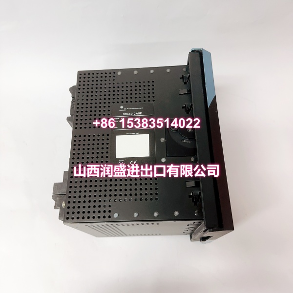
- Model: 469-P1-HI-A20-E
- Brand: GE Multilin
- Series: 469 Motor Management Relay
- Core Function: Protects and monitors medium/large three-phase AC motors using thermal modeling, current-based fault detection, metering, analog retransmission, and serial communication.
- Product Type: Motor Management / Motor Protection Relay
- Key Specs: 1 A phase CT input | HI control power 90–300 VDC / 70–265 VAC | 4×4–20 mA analog outputs | Enhanced LCD
- Condition: New Original / New Surplus
Key Technical Specifications
- Part Number: 469-P1-HI-A20-E
- Product Family: GE Multilin 469 Motor Management Relay
- Phase CT Input: P1 option, 1 A phase CT secondaries
- Control Power: HI option, 90–300 VDC / 70–265 VAC, 48–62 Hz
- Analog Outputs: 4 isolated 4–20 mA outputs (A20 option)
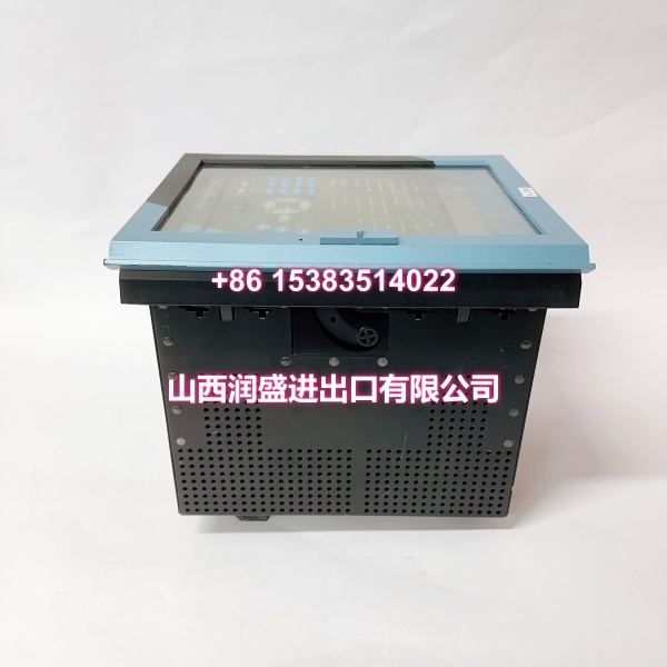
- Display: Enhanced display with larger LCD (E option)
- Harsh Environment Coating: Not included; no “H” suffix in this build
- Communication: RS485 Modbus RTU standard; front-panel RS232 service port
- Digital Inputs: 9 opto-isolated inputs (base unit)
- Analog Inputs: 4 analog inputs, configurable for 4–20 mA / 0–20 mA / 0–1 mA
- RTD Inputs: Supported on the 469 platform; not indicated by this specific option code
- Metering: Built-in metering functions standard on the 469 series
- Configuration Software: EnerVista 469 Setup
- Operating Temperature: Typically −40°C to +60°C
Product Introduction (No Fluff)
The GE Multilin 469-P1-HI-A20-E is a medium/large AC motor management relay built for switchgear and MCC applications. It provides thermal overload protection, stall/jam supervision, phase unbalance, ground fault monitoring, event recording, and analog signal retransmission.
This configuration is defined by 1 A CT inputs, wide-range HI control power, four 4–20 mA analog outputs, and an enhanced LCD. Matching the exact option code matters during replacement, especially when CT secondary rating and analog output scaling are tied into existing DCS/PLC loops.
QA & Testing SOP (Dynamic & Transparent)
For a motor protection relay, we validate protection logic, analog outputs, and communication before release.
- Label and option verification: Confirm 469-P1-HI-A20-E on the nameplate. Verify P1 (1 A CT), HI supply, A20 (4–20 mA), E (enhanced display), and no H suffix.
- Physical inspection: Check rear terminals, drawout case contacts, front-panel keypad, LCD, and connector integrity. Reject units with cracked housings, corroded terminals, or damaged displays.
- Control power test: Apply rated HI control power and verify normal boot, LCD initialization, and LED status behavior.
- Secondary injection check: Use a relay test set to inject phase and ground current signals. Verify trip/alarm responses for overload, stall, unbalance, and ground fault functions according to configured setpoints.
- Analog output validation: Confirm each 4–20 mA output scales correctly against configured parameters such as thermal capacity, motor load, or RTD temperature.
- Communication validation: Verify RS485 Modbus RTU addressing and front-panel RS232 connectivity. Confirm EnerVista 469 access if the port is enabled.
- ESD-safe handling: Pack in anti-static bags with foam support. Include part number, option code, and test status on the shipping label.

Installation Pitfalls & Guide (Engineer to Engineer)
❗ CT secondary rating must match. This is a P1 unit designed for 1 A CT secondaries. Connecting it to 5 A CT circuits will produce incorrect current measurement and unreliable protection.
❗ Analog output scaling must be verified. The A20 option provides 4–20 mA outputs, but each channel must be mapped to the correct parameter and range before tying into a DCS or PLC.
❗ Do not assume communication settings carry over. Modbus address, baud rate, and parity must match the existing network. A relay can power up normally and still remain offline.
❗ Check drawout case contacts. Poor seating or oxidized case pins can cause intermittent communication, missing analog outputs, or false I/O alarms.
Replacement steps:
- Pre-install: Record existing setpoints, CT ratios, analog output mappings, Modbus settings, and digital I/O assignments. De-energize the control circuit safely.
- Removal: Label all CT, analog, digital I/O, and communication wires. Remove the relay from the drawout case without forcing terminals.
- Install: Seat the new unit firmly, verify CT polarity, analog output wiring, control power, and RS485 termination.
- Power-on test: Restore control power, load settings via EnerVista 469, verify metering and analog outputs, and perform a controlled secondary injection test before returning the motor to service.
Technical FAQ
Is this a direct replacement for my existing 469 relay?
Only if the option code matches. This unit is 469-P1-HI-A20-E, meaning 1 A CT input, HI control power, 4–20 mA analog outputs, enhanced LCD, and no harsh-environment coating. Swapping in a P5, A1, or H-coded unit can change CT compatibility, analog scaling, or environmental rating.
Can I connect this to 5 A CTs?
No. The P1 option is for 1 A CT secondaries. Using 5 A CTs without matching interposing CTs or rewiring will cause incorrect protection behavior.
Does this model include RTD inputs?
The 469 platform supports RTD monitoring, but this specific part number does not carry an explicit RTD option code. If stator or bearing temperature monitoring is required, confirm the exact installed configuration before replacement.
What communication does it support?
RS485 Modbus RTU is standard, with a front-panel RS232 port for local configuration. Ethernet or DeviceNet depend on other submodels and are not indicated by this part number.
Is this product still in production?
GE Vernova has discontinued manufacturing of the 469 series. The recommended alternatives are the 859 or 869 relays, but migration requires setpoint review, I/O mapping, and communication revalidation.