Product Core Brief
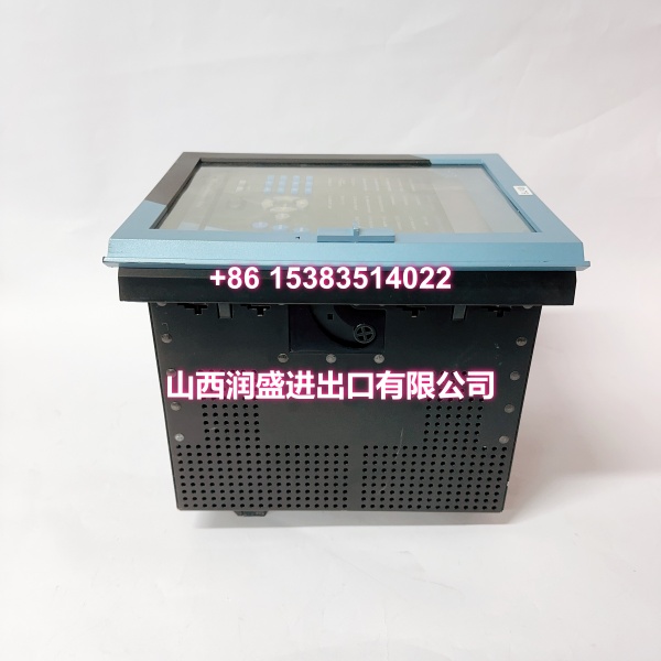
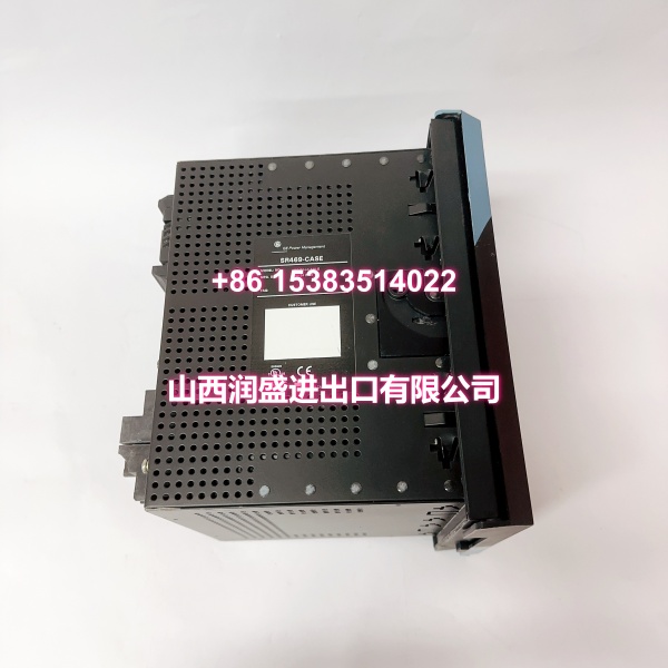
- Model: 469-P1-HI-A20
- Brand: GE Multilin
- Series: Multilin 469 Motor Management Relay
- Core Function: Microprocessor-based protection and management for medium-voltage motors with thermal modeling, differential protection, and analog retransmission.
- Product Type: Motor Management Relay (Draw-Out)
- Key Specs: P1 = 1 A CT secondary | HI = 90–300 VDC / 70–265 VAC | A20 = four 4–20 mA analog outputs
- Condition: New Original / New Surplus (subject to available stock)
Key Technical Specifications
- Part Number: 469-P1-HI-A20
- Product Type: Motor Management Relay
- Construction: Draw-out chassis (minimizes replacement downtime)
- Phase CT Secondary: 1 A (P1 option)
- Control Power (HI): 90–300 VDC / 70–265 VAC, 48–62 Hz
- Analog Outputs: 4 × 4–20 mA isolated (A20 option)
- Digital Inputs: 9 opto-isolated
- RTD Inputs: Up to 12 channels (3-wire Pt100/Ni120 compatible)
- Ground CT Input: Dedicated ground CT channel
- Differential Protection: Single-CT differential supported
- Communication: RS-232 (front), 2 × RS-485 (Modbus RTU); optional Ethernet/DeviceNet
- Display: 40-character alphanumeric LCD with status LEDs
- Output Relays: 6 programmable relays
- Operating Temperature: -40°C to +60°C
- Enclosure Rating: IP40-X, panel/switchgear mount
- Configuration Software: EnerVista 469
Product Introduction (No Fluff)
The GE Multilin 469-P1-HI-A20 is a draw-out motor management relay built for medium-voltage, high-horsepower motors. It combines thermal overload protection, single-CT differential protection, ground fault detection, and four isolated 4–20 mA analog outputs into one panel-mounted unit. The P1 suffix means it is configured for 1 A CT secondaries, while the HI power supply accepts 90–300 VDC or 70–265 VAC.
For plant engineers managing critical motors—fans, compressors, pumps, or mills—this relay provides both protection and asset monitoring. The A20 analog output pack lets you retransmit current, thermal capacity, or power readings directly to a DCS or PLC without adding external transducers. The draw-out chassis means you can swap the relay during a maintenance window without rewiring the terminal blocks.
QA & Testing SOP (Dynamic & Transparent)
Surplus 469 relays need thorough verification before they go into a switchgear cell. Here is our process:
- Part Number & Firmware Verification: Confirm the rear label reads 469-P1-HI-A20 exactly. Power up via the front RS-232 port and log the firmware revision through EnerVista 469.
- Self-Test & Diagnostics: Run the relay’s built-in self-test. Check for any stored watchdog errors, EEPROM faults, or output relay failures.
- Control Power Burn-In: Apply HI-range control power and let the unit stabilize. Verify the display boots cleanly and all status LEDs illuminate correctly.
- CT & Differential Input Check: Inject a known 1 A secondary current through the phase CT inputs. Verify current readings match the test set and confirm differential protection thresholds respond correctly.
- Analog Output Validation: Loop each of the four 4–20 mA outputs. Verify they scale correctly across the full range (e.g., 4 mA at 0%, 20 mA at 100% of the programmed variable).
- Communication & Packaging: Test RS-485 Modbus RTU communication. Confirm register reads match displayed values. Pack in anti-static bags with foam cushioning.
Installation Pitfalls & Guide (Engineer to Engineer)
CT secondary must match the P1 rating. This unit is built for 1 A CT secondaries. Connecting it to 5 A CTs will give you incorrect readings and can damage the input circuitry over time.
Draw-out chassis requires proper seating. The relay must be fully inserted and latched before applying control power. A partially seated unit can cause intermittent CT connections and nuisance trips.
Analog output grounding matters. The A20 outputs are isolated, but mixing ground references between the relay and the receiving PLC/DCS can cause offset errors. Use a single-point ground for the analog loop.
Differential CT wiring polarity is critical. If you are using single-CT differential protection, reversed polarity on the differential CT will cause an immediate false trip on start.
Replacement Steps:
- Pre-install: Verify the full model code, back up existing settings via EnerVista 469, and prepare LOTO.
- Removal: Unlock the draw-out handle, slide the old relay out, and label any loose wiring if terminals were disturbed.
- Install: Slide the new relay in until it seats fully. Lock the draw-out handle. Verify CT polarity and analog output wiring.
- Power-on Test: Apply control power, load the saved settings, inject test current, and confirm trip/alarm outputs before returning the motor to service.
Technical FAQ
1. What does “P1” vs “P5” mean? P1 = 1 A CT secondary, P5 = 5 A CT secondary. You must match the relay to your existing CTs. Mixing them will cause incorrect current readings and can damage the relay’s input circuit.
2. What does the “A20” option add? Four isolated 4–20 mA analog outputs. These let you retransmit measured values (motor current, thermal capacity used, kW, etc.) to a DCS or PLC for trending and alarming without external transducers.
3. Can I add Ethernet or RTD inputs in the field? Ethernet and DeviceNet are field-installable options on the 469 platform. RTD inputs depend on the specific hardware configuration ordered. If your unit did not ship with RTD hardware, you would need to verify field upgrade availability with the manufacturer or a certified service provider.
4. Is the 469 series still in production? No. GE Vernova has discontinued manufacturing of the 469 series. The recommended replacement platforms are the Multilin 859 or 869 relays. Surplus 469 units remain a practical option for like-for-like replacements where re-engineering the switchgear is not feasible.
5. What warranty do you offer on surplus stock? Terms vary by condition and availability. For surplus industrial relays, we typically provide a short functional guarantee. Confirm details at time of order.