Product Core Brief
- Model: 200-566-000-012
- Brand: VIBRO (Vibro-Meter)
- Series: VM600 Machine Protection System
- Core Function: Digital I/O expansion module for discrete status monitoring and machine protection signaling.
- Product Type: Digital I/O Expansion Module
- Key Specs: High-level electrical isolation | Discrete input/output channels | VM600 rack-compatible
- Condition: New Surplus
Product Introduction
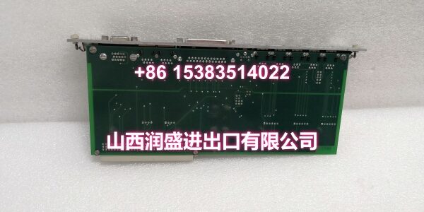
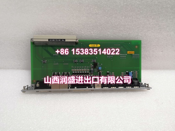
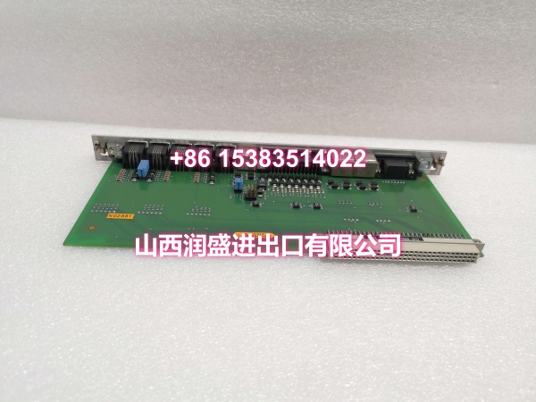
VIBRO 200-566-000-012 is a digital I/O expansion module designed for Vibro-Meter VM600 machine protection systems. It brings discrete field signals—such as relay trips, permissive contacts, and alarm states—into the protection rack for monitored rotating equipment.
This module supports high-level electrical isolation to reduce noise coupling from field wiring. It is commonly used in turbine, compressor, and generator protection schemes where discrete alarms, interlocks, and status feedback must be processed reliably. Exact channel counts and electrical ratings should be confirmed against the official Vibro-Meter datasheet for this specific part number.
Key Technical Specifications
| Parameter | Value |
|---|---|
| Product Type | Digital I/O Expansion Module |
| Brand | VIBRO / Vibro-Meter |
| System Compatibility | VM600 Machine Protection System |
| Function | Discrete digital input/output expansion |
| Isolation | High-level electrical isolation |
| Typical Use | Machine protection, alarm signaling, interlock monitoring |
| Mounting | VM600 19″ rack module |
| Communication | Backplane integration with VM600 system |
| Condition | New Surplus |
Quality Control Process
Each unit begins with a visual inspection of the front panel, connectors, PCB, and rack contacts for corrosion, bent pins, or thermal stress. The module is then seated into a compatible VM600 rack to verify mechanical fit and backplane communication.
Discrete inputs are checked with dry-contact simulation to confirm channel recognition and debounce behavior. Outputs are verified with a multimeter and load simulation to ensure proper switching and isolation. Backplane communication is tested to confirm the module is recognized by the rack controller. Final packing uses anti-static bags, foam inserts, and sealed cartons to protect the module during transit.
Replacement Pitfall Guide
❗ Confirm the exact part number and revision. VIBRO IOCN modules look similar across variants, but channel counts, logic polarity, and firmware behavior can differ. Installing the wrong variant can cause missed alarms or incorrect interlock states.
❗ Check input logic polarity before commissioning. Some modules expect dry-contact closure to 24V, others to common. Swapping polarity can make an active alarm appear inactive—or worse, mask a trip condition entirely.
❗ Verify backplane addressing and slot configuration. VM600 modules must be recognized in the correct slot with the correct configuration. A module that powers up but does not appear in the rack map will not participate in protection logic.
❗ Review isolation and grounding practices. High-level isolation helps, but ground loops from field wiring can still create false triggers. Keep field wiring separated from analog sensor cables and confirm shield termination at one end only.
Keep these in mind and you’ll cut 90% of rework time.
Compatibility Matrix & Benchmarks
| Original Model | Replacement / Successor Model | Compatibility Level | Migration Notes |
|---|---|---|---|
| VIBRO 200-566-000-012 | VIBRO 200-566-000-012 | Direct | Same part number; verify rack firmware and channel configuration. |
| VIBRO 200-566-000-012 | VIBRO IOCN 200-566-000-112 | Needs Adaptation | Similar IOCN family; channel count and configuration must be verified. |
| VIBRO 200-566-000-012 | VIBRO VM600 RLC16 Relay Module | Needs Adaptation | Different module type; relay output only, not a direct I/O replacement. |
Benchmark notes:
- Designed for VM600 machine protection racks with high-level electrical isolation.
- Supports discrete alarm, trip, and status signaling for rotating equipment protection.
Always confirm the exact channel map, logic polarity, and rack configuration against the original unit before installation.