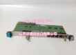
Product Core Brief
- Model: L54E2900WF00
- Board Code: BCSR1
- Brand: ALSTOM
- Series: ALSTOM Legacy Excitation / Relay & Control Cabinet Platform
- Core Function: Rack-level backplane or relay interface PCB supporting slot mounting, internal bus routing, power distribution, and relay/I/O signal interconnection.
- Product Type: Excitation Cabinet PCB / Backplane or Relay Interface Board / Spare Control Card
- Key Specs: Rack slot-mounted | Internal bus and signal routing | Relay interface function indicated by BCSR1 code | Industrial cabinet application
- Condition: New Original / New Surplus
Product Introduction
ALSTOM L54E2900WF00 BCSR1 is an ALSTOM cabinet PCB identified by the board code BCSR1. It is typically referenced as a spare or replacement board for ALSTOM legacy excitation, relay, and control cabinet systems.
In public spare listings, L54E2900WF00 is associated with BCSR1 and appears alongside related ALSTOM backplane and interface boards such as BCEL2 L54E2900WB00 and BCSA1 L54E2900WH00. This suggests that BCSR1 is part of the same family of rack-level boards used for internal bus routing, relay interfacing, and cabinet signal distribution.
Because public sources do not clearly define whether BCSR1 is a pure backplane, relay output board, or mixed-function interface card, the exact function must be confirmed from the installed nameplate, cabinet drawing, or system documentation before replacement.
Key Technical Specifications
| Parameter | Value |
|---|---|
| Full Model | ALSTOM |
| Board Code | |
| Product Type | Excitation Cabinet PCB / Backplane or Relay Interface Board |
| System Platform | ALSTOM Legacy Excitation / Relay & Control Cabinet Platform |
| Core Function | Rack-level bus routing, relay interface, and signal distribution |
| Power Supply | Confirm per installed nameplate |
| Communication / I/O | Internal backplane bus and relay/I/O signal routing |
| Installation | Rack slot-mounted in ALSTOM cabinet |
| Typical Applications | Generator excitation cabinets, relay panels, substation and industrial control racks |
| Operating Environment | Industrial control room; ventilated cabinet |
Quality Control Process
- Visual and code check: Confirm L54E2900WF00 and BCSR1 markings match the replaced PCB.
- Slot and connector inspection: Check PCB edge connector, slot guides, and cabinet backplane condition.
- Power and insulation check: Verify supply voltage, polarity, and insulation before energizing.
- Bus and relay check: Confirm internal bus routing, relay outputs, status indicators, and fault signals.
- Final packing: Record test results, apply asset labels, and ship in anti-static packaging with connector protection.
Replacement Pitfall Guide
❗ Confirm BCSR1 vs BCEL2/BCSA1. L54E2900WF00 is associated with BCSR1, while L54E2900WB00 is linked to BCEL2 and L54E2900WH00 to BCSA1; these are not interchangeable without verification.
❗ Verify exact board function. BCSR1 may be a backplane, relay interface, or mixed-function board; do not assume function from part number alone.
❗ Check slot position and addressing. Incorrect placement can affect bus communication, relay outputs, or cabinet interlocks.
❗ Validate relay and fault signals after replacement. Even if the board powers up, relay outputs and protection signals must be checked against cabinet documentation.
Keep these in mind and you’ll cut 90% of rework time.
Compatibility Matrix & Benchmarks
| Original Model | Replacement / Successor Model | Compatibility Level | Migration Notes |
|---|---|---|---|
| ALSTOM | ALSTOM | Direct | Like-for-like replacement when cabinet, slot, and board code match. |
| ALSTOM | ALSTOM BCSR1 variant | Needs Adaptation | Confirm exact part number, function, and cabinet compatibility. |
| ALSTOM | ALSTOM BCEL2/BCSA1 or other L54E2900 boards | Needs Adaptation | Different board codes serve different functions; substitution requires verification. |
- Typical use: ALSTOM legacy excitation cabinets, relay panels, substation automation, and industrial control racks.
- Key verification points: L54E2900WF00 part number, BCSR1 board code, host cabinet model, slot position, board function, and relay/bus configuration.