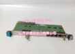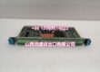
Product Core Brief
- Model: AH116-2
- Brand: ALSTOM
- Series: Industrial Servo Control Board
- Core Function: Servo control board for precise position, speed, and torque control of actuators and servo drives.
- Product Type: Servo Control Circuit Board
- Key Specs: 0–10 V DC analog output | 50 kHz output frequency | RS485 / CAN / Modbus / EtherNet/IP interfaces
- Condition: New Original / New Surplus
Product Introduction
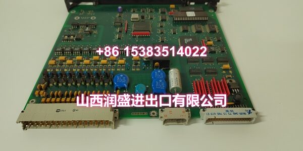
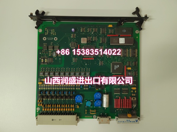
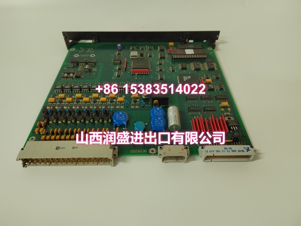
ALSTOM AH116-2 is a servo control circuit board used to regulate position, speed, and torque in industrial motion and actuator systems. It processes sensor feedback and issues analog control outputs to servo drives or hydraulic/electric actuators.
The board supports 0–10 V DC analog output, up to 50 kHz frequency range, and common industrial interfaces including RS485, CAN, Modbus, and EtherNet/IP. Exact channel count, firmware revision, and mechanical form factor should be confirmed from the installed nameplate before commissioning.
Key Technical Specifications
| Parameter | Value |
|---|---|
| Full Model | M |
| Product Type | Servo Control Circuit Board |
| Control Function | Position, speed, and torque control |
| Analog Output | 0–10 V DC |
| Output Frequency | 50 kHz (adjustable range 20–60 kHz) |
| Communication Interfaces | RS485, CAN, Modbus, EtherNet/IP |
| Analog Inputs | 4 channels (to be confirmed per variant) |
| Digital Inputs | 8 channels (to be confirmed per variant) |
| Digital Outputs | 4 channels (to be confirmed per variant) |
| Supply Voltage | 24 V DC or 220 V AC, depending on variant |
| Operating Temperature | -20 °C to +60 °C |
| Protection | Overload, overheat, overvoltage, short-circuit protection |
Quality Control Process
- Visual and revision check: Inspect PCB condition, connectors, mounting hardware, and AH116-2 labeling for consistency with site records.
- Power and isolation check: Verify supply rails and insulation with a Fluke multimeter before connecting servo loads.
- Analog output test: Use an oscilloscope to confirm 0–10 V DC output range, frequency stability, and signal noise under no-load and loaded conditions.
- I/O and communication check: Validate analog/digital channel response and RS485/CAN/Modbus communication with a signal generator and protocol tester.
- Final packing: Record test results, apply asset labels, and ship in anti-static packaging with edge protection for connectors.
Replacement Pitfall Guide
❗ Confirm supply voltage variant. Some installations run 24 V DC; others use 220 V AC. Wrong supply voltage can destroy the board instantly.
❗ Verify analog output scaling. A 0–10 V DC output must match the servo drive’s input range; incorrect scaling causes position drift or runaway motion.
❗ Check communication protocol settings. RS485, CAN, and Modbus addresses or baud rates must match the existing network, or the board will appear offline.
❗ Don’t ignore grounding and shielding. Servo control lines are sensitive to noise; poor grounding near VFDs or motors can create false position feedback.
Keep these in mind and you’ll cut 90% of rework time.
Compatibility Matrix & Benchmarks
| Original Model | Replacement / Successor Model | Compatibility Level | Migration Notes |
|---|---|---|---|
| M | M | Direct | Like-for-like replacement when voltage variant and pinout match. |
| M | ALSTOM servo control board successor | Needs Adaptation | Confirm analog output range, communication protocol, and I/O mapping. |
| M | Third-party servo controller | Needs Adaptation | Requires full re-engineering of wiring, scaling, and control logic. |
- Typical use: Servo position/speed/torque control for actuators, drives, and motion systems.
- Key verification points: 0–10 V DC output, 50 kHz frequency range, supply voltage variant, and communication interface match.