Product Core Brief
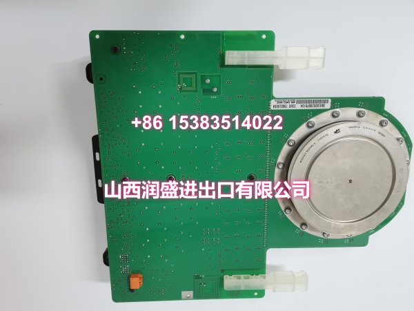
- Model: 5SHX1960L0004 (3BHL000390P0104)
- Brand: ABB
- Series: ABB 5SHX High-Power IGCT Series
- Core Function: High-power integrated gate commutated thyristor module for medium-to-high voltage energy conversion in industrial drives, HVDC, and grid stabilization systems.
- Product Type: Integrated Gate Commutated Thyristor (IGCT) Module
- Key Specs: ~6 kV Voltage Class | Light-Triggered Gate Interface | Reverse-Conducting Design | Press-Pack Package | High Surge Current Capability
- Note: Condition: New Original (New Surplus). Origin: Sweden.
Key Technical Specifications
| Parameter | Value |
|---|---|
| Manufacturer Part Number | 3BHL000390P0104 |
| Device Model | 5SHX1960L0004 |
| Device Type | Integrated Gate Commutated Thyristor (IGCT) |
| Series | ABB 5SHX High-Power IGCT Series |
| Voltage Class | ~6 kV (device family rated for 6000V-class systems) |
| Current Rating | High-current class (suitable for multi-MVA converters) |
| Internal Structure | Reverse-conducting: IGCT switching element + integrated anti-parallel diode |
| Gate Interface | Light-triggered gate interface (fiber optic communication) |
| Switching Characteristics | Fast turn-on/turn-off with controlled di/dt and dv/dt |
| Surge Current Capability | High non-repetitive surge current rating for fault ride-through |
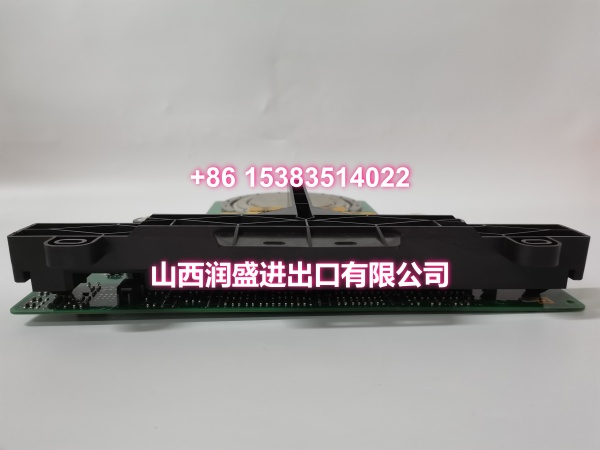
| Thermal Interface | Press-pack / hockey-puck package with double-sided cooling compatibility |
| Mounting Method | Press-fit into converter stack with clamping force |
| Operating Temperature | Junction temperature range per ABB spec (typically -40°C to +125°C Tj max) |
| Typical Applications | Medium-voltage drives (ACS6000), HVDC transmission, STATCOM, SVC, large industrial inverters |
| Origin | Sweden |
| Condition | New Original (New Surplus) |
Product Introduction
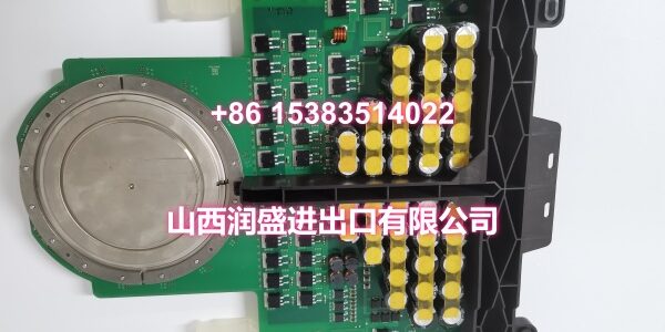
The ABB 5SHX1960L0004 (order code 3BHL000390P0104) is a high-power integrated gate commutated thyristor (IGCT) module from ABB’s 5SHX series. It integrates an IGCT switching element with an anti-parallel diode in a single press-pack device, featuring a light-triggered gate interface via fiber optic communication—eliminating the need for external snubber circuits and providing electrical isolation between the control system and the high-voltage power circuit.
The 5SHX1960L0004 is rated for the ~6 kV voltage class and is designed for megawatt-level power conversion in medium-to-high voltage drive systems such as the ABB ACS6000, as well as HVDC transmission, STATCOM reactive power compensation, SVC static var systems, and large industrial inverters for mining, oil & gas, and metals processing. The light-triggered gate interface provides superior noise immunity compared to electrical gate connections, making it ideal for electrically noisy environments like furnace control panels and high-voltage switchyards.
The reverse-conducting design (IGCT + integrated free-wheeling diode) reduces component count in the converter bridge, lowers stray inductance, and improves overall system reliability. The IGCT architecture delivers significantly lower conduction and switching losses compared to conventional GTO technology, while maintaining the high-voltage blocking capability required for medium-voltage grid applications.
For engineers maintaining or upgrading legacy high-power installations, this module is a direct drop-in replacement for failed or end-of-life IGCTs in ABB converter stacks. The Swedish-origin press-pack construction ensures compatibility with existing clamping hardware and heat sink interfaces, avoiding costly mechanical rework.
QA & Testing SOP
Every unit goes through a structured verification process before shipment:
- Visual Inspection: Check the press-pack housing for cracks, corrosion on the anode/cathode contact surfaces, and physical damage to the ceramic insulation. Verify that the fiber optic gate connector is intact and undamaged.
- Contact Surface Verification: Inspect the anode and cathode contact surfaces for flatness, pitting, or oxidation. Surface imperfections cause uneven current distribution and localized hot spots under high-current operation, leading to premature thermal runaway.
- Fiber Optic Gate Verification: Inspect the fiber optic gate connector for cleanliness and physical damage. A contaminated or damaged fiber optic interface can cause gate signal loss, leading to device misfiring or failure to turn on.
- Blocking Voltage Test (Leakage Current): Where test infrastructure allows, apply rated forward and reverse blocking voltage and measure leakage current. Excessive leakage indicates degraded junction integrity and reduced voltage margin.
- Trigger Verification: Apply a gate trigger pulse via the fiber optic interface and verify the device turns on correctly. This confirms the light-triggered gate structure and internal trigger circuitry are functional.
- Anti-Counterfeit & Packaging: Verify authenticity markings on the device body. Each unit is shipped in protective packaging with desiccant to prevent moisture absorption and contact surface oxidation during transit.
Installation Pitfalls & Guide
Replacing a press-pack IGCT with a light-triggered gate interface requires attention to both mechanical precision and optical signal integrity.
❗ Clamping Force Specification: The press-pack IGCT requires a specific clamping force to ensure low thermal and electrical contact resistance. Under-clamping causes high contact resistance, leading to localized heating and device failure. Over-clamping can crack the ceramic housing or damage the silicon die. Always use a calibrated torque wrench and follow ABB’s specified clamping force/torque sequence for the specific device size.
❗ Heat Sink Surface Preparation: The heat sink mating surface must be clean, flat, and free of oxidation. Apply a thin, even layer of thermal interface compound (silicone grease or phase-change material) before installation. Air gaps between the device and heat sink create thermal bottlenecks that cause junction temperature to exceed limits under load.
❗ Fiber Optic Gate Connection: The light-triggered gate interface requires a clean, undamaged fiber optic cable and connector. Contamination on the fiber optic end-face (dust, oil, scratches) can attenuate the gate trigger signal, causing the device to fail to turn on or turn on slowly—leading to excessive switching losses and potential device destruction. Always use protective caps on unused fiber optic connectors and clean the end-face with appropriate fiber optic cleaning tools before mating.
❗ Snubber Circuit Verification: While IGCTs are designed for snubberless operation in many applications, some converter topologies still use RC snubbers across the device. Verify that snubber components (if present) are within specification before energizing the converter—a failed snubber capacitor or resistor can cause destructive dv/dt stress on the replacement IGCT.
4-Step Replacement Guide:
- Pre-install: Document the clamping force specification, fiber optic gate wiring configuration, and snubber circuit values from the existing converter documentation. Verify the heat sink surface is clean and flat. Back up the drive/converter control parameters.
- Removal: Disconnect all power and verify zero voltage on the DC bus. Discharge all capacitors. Disconnect the fiber optic gate cable carefully—avoid bending the fiber beyond its minimum bend radius. Loosen the clamping mechanism in the specified sequence (typically a cross-pattern) to avoid uneven stress. Remove the old device and clean the heat sink surface thoroughly.
- Install: Apply thermal interface compound to the heat sink surface. Position the new IGCT with correct anode/cathode orientation. Tighten the clamping mechanism in the specified sequence to the specified torque/force. Connect the fiber optic gate cable carefully, ensuring the connector seats fully and the locking mechanism engages.
- Power-on Test: Apply control power first and verify gate trigger signals are present and correct at the device terminals (monitor via fiber optic test points if available). Apply main power at reduced voltage if possible. Monitor device temperature and gate trigger waveforms during initial operation. Verify normal switching behavior before returning to full load.
Technical FAQ
1. What’s the difference between light-triggered and electrically-triggered IGCTs? Light-triggered IGCTs use a fiber optic cable to deliver the gate trigger signal, while electrically-triggered IGCTs use a copper wire connection. The light-triggered design provides complete electrical isolation between the low-voltage control system and the high-voltage power circuit, eliminating ground loop issues and providing superior noise immunity in electrically noisy environments. However, light-triggered IGCTs require careful handling of the fiber optic cable and connectors to avoid signal attenuation.
2. What does “reverse-conducting” mean for this device? The 5SHX1960L0004 integrates both the IGCT switching element and an anti-parallel free-wheeling diode in a single press-pack package. This eliminates the need for a separate diode in the converter bridge, reducing component count, stray inductance, and installation complexity. The integrated diode is optimized for fast recovery to match the IGCT’s switching speed.
3. Can I substitute a different IGCT or GTO for the 5SHX1960L0004? IGCTs and GTOs are not directly interchangeable without verifying voltage rating, current rating, gate drive requirements (light-triggered vs. electrically-triggered), mechanical dimensions, and clamping force specifications. Even within the ABB 5SHX series, different suffixes indicate different voltage/current ratings and gate interface types. Always match the exact part number or consult ABB’s cross-reference documentation before substitution.
4. What converter systems use the 5SHX1960L0004? The 5SHX1960L0004 has been deployed in medium-to-high voltage drive systems such as the ABB ACS6000, as well as HVDC transmission converters, STATCOM reactive power compensation systems, SVC static var systems, and large industrial inverters for mining, oil & gas, and metals processing applications.
5. What’s the difference between New Surplus and Refurbished for press-pack IGCTs? We supply this unit as New Original (New Surplus)—unused, original factory stock. This comes with a standard 12-month warranty. Refurbished press-pack IGCTs carry significant risks including degraded silicon junctions from previous overvoltage events, damaged contact surfaces from previous clamping cycles, and undocumented gate junction degradation. Press-pack devices are particularly sensitive to contact surface condition—refurbished units may have microscopic surface damage that causes thermal runaway under high-current operation. Refurbished units typically come with 30-90 day limited warranties that don’t cover latent thermal failures.