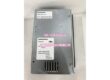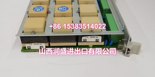
Product Core Brief
- Model: 500MTM02 (1MRB150020R1102 / 1HDF930512X010)
- Brand: ABB
- Series: ABB AC 500 Series PLC Platform
- Core Function: 8-channel temperature measurement module for acquiring thermocouple and RTD sensor signals in process control applications.
- Product Type: Analog Temperature Input Module
- Key Specs: 8 Analog Input Channels | TC & RTD Sensor Support | Channel-to-Channel Isolation | -25°C to +60°C Operating Range
- Note: Condition: New Original (New Surplus).
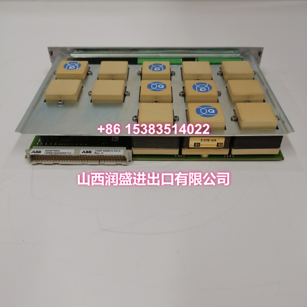
Key Technical Specifications
| Parameter | Value |
|---|---|
| Manufacturer Part Number | 1MRB150020R1102 / 1HDF930512X010 |
| Device Model | 500MTM02 |
| Functional Type | Temperature Measurement / Analog Input Module |
| Parent System | ABB AC 500 Series PLC |
| Input Channels | 8 independent analog input channels |
| Supported Sensors | Thermocouples (J, K, T, E, R, S, B, N) and RTDs (Pt100, Pt1000, Ni100, Ni1000, Cu50, Cu100) |
| Measurement Range | TC: -200°C to +1800°C (varies by type) |
| Measurement Accuracy | TC: ±0.1°C (-50°C to +150°C) or ±0.1% FS (outside range) |
| Sampling Rate | 10 Hz per channel (max) |
| Electrical Isolation | 500 VAC channel-to-channel isolation; power-to-signal isolation |
| Power Supply | 24 VDC (±10% to ±20%), power consumption ≤6 W |
| Wiring Method | Removable terminal blocks (spring-loaded or screw-type) |
| Mounting Method | Plug-in module for AC 500 system rack |
| Operating Temperature | -25°C to +60°C |
| Relative Humidity | 5%–95% (non-condensing) |
| Condition | New Original (New Surplus) |
Product Introduction
The ABB 500MTM02 (order codes 1MRB150020R1102 / 1HDF930512X010) is an 8-channel temperature measurement module for the ABB AC 500 series PLC platform. It acquires temperature signals from thermocouple and RTD sensors across the plant and converts them into digital values for the PLC’s control logic, enabling precise temperature monitoring and regulation in process control, energy management, and equipment protection applications.
Each of the 8 channels supports independent sensor type configuration, allowing mixed thermocouple and RTD inputs on the same module. The 500 VAC channel-to-channel isolation prevents a fault on one sensor circuit from propagating to adjacent channels or the PLC backplane—a critical feature in electrically noisy environments like furnace control panels and reactor skids. For engineers maintaining brownfield AC 500 installations, this module is a direct drop-in replacement that restores temperature acquisition without reworking field wiring or reassigning channel addresses.
QA & Testing SOP
Every unit goes through a structured verification process before shipment:
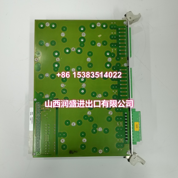
- Visual Inspection: Check for burnt components, swollen capacitors, corrosion on the backplane connector pins, and physical damage to the front-panel terminal blocks. Verify that all terminal screws or spring clips are present and undamaged.
- Backplane Connector Verification: Inspect the DIN 41612-style backplane connector for bent or pushed-out pins. A poor backplane connection is the most common cause of intermittent channel readings and module communication faults.
- Channel Continuity & Isolation Test: Using a multimeter and megohmmeter, verify each channel’s input circuit is intact and that channel-to-channel isolation meets the 500 VAC specification. This catches latent insulation breakdown that causes cross-channel interference.
- Sensor Simulation Test: Where test infrastructure allows, connect known thermocouple and RTD simulation sources to each channel and verify the module reports accurate temperature values within the specified accuracy band. This confirms the ADC and cold-junction compensation circuitry are functional.
- Anti-Counterfeit & Packaging: Verify authenticity markings on the PCB and label. Each unit is shipped in anti-static packaging with desiccant to prevent moisture damage during transit.
Installation Pitfalls & Guide
Replacing a temperature input module seems straightforward, but there are a few traps that cause persistent measurement errors:
❗ Thermocouple Wire Type Mismatch: Each thermocouple type (J, K, T, etc.) has a different voltage-to-temperature curve. If the module’s channel configuration in the PLC software doesn’t match the actual sensor type wired to that channel, the temperature reading will be significantly wrong—even though the hardware is functioning correctly. Always verify the sensor type label on the field wiring matches the software configuration.
❗ RTD Wiring Mode Configuration: RTDs support 2-wire, 3-wire, and 4-wire connections. The 3-wire and 4-wire modes compensate for lead resistance, while 2-wire mode does not. If your field wiring is 3-wire but the channel is configured for 2-wire, you’ll get a consistent positive offset error proportional to the lead resistance. Match the wiring mode in software to the physical connection.
❗ Cold Junction Compensation (CJC) Error: Thermocouple measurements require accurate cold junction compensation. The 500MTM02 has an internal CJC sensor, but if the module is installed near a heat source (like a power supply or SSR) inside the cabinet, the CJC reference temperature will be elevated, causing all thermocouple readings to drift low. Ensure adequate clearance around the module for airflow.
❗ Shield Grounding for Thermocouples: Thermocouple extension wires should use shielded cable with the shield grounded at the module end only. Grounding at both the sensor and the module creates ground loops that introduce 50/60 Hz noise into the microvolt-level thermocouple signal, causing unstable readings.
4-Step Replacement Guide:
- Pre-install: Document the sensor type, wiring mode (2/3/4-wire for RTDs), and channel scaling for each of the 8 channels from the existing PLC program or I/O list. Note any channel-specific alarm thresholds.
- Removal: Power down the AC 500 rack. Label each field wire before disconnecting from the old module’s terminal block. Remove the old module straight out using the ejector levers.
- Install: Insert the new module firmly into the correct slot on the rack, ensuring the backplane connector seats fully. Reconnect field wires to the correct channel terminals per your labels.
- Power-on Test: Power up the rack. Verify the module’s status LED indicates normal operation. Compare live temperature readings from each channel against known process values or a handheld reference thermometer. Adjust channel configuration in the PLC software if needed to match sensor types and wiring modes.
Technical FAQ
1. What sensor types does the 500MTM02 support? The module supports standard thermocouple types (J, K, T, E, R, S, B, N) and RTD types (Pt100, Pt1000, Ni100, Ni1000, Cu50, Cu100). Each of the 8 channels can be independently configured for a different sensor type, allowing mixed inputs on the same module.
2. Can I mix thermocouple and RTD sensors on the same module? Yes. Each channel is independently configurable, so you can have thermocouple sensors on some channels and RTD sensors on others within the same 500MTM02 module. Just ensure the channel configuration in the PLC software matches the physical sensor on each terminal.
3. What’s the measurement accuracy? For thermocouples: ±0.1°C in the -50°C to +150°C range, or ±0.1% of full scale outside that range. For RTDs: ±0.05°C in the 0°C to +100°C range, or ±0.05% of full scale outside that range. Actual accuracy depends on proper wiring, correct sensor type configuration, and stable cold junction compensation.
4. Can I hot-swap this module? The AC 500 platform supports hot-swapping for certain I/O modules when properly configured in system parameters. However, removing a temperature module while the process is running will cause all 8 channels to go to a fault state, potentially triggering process alarms or safety interlocks. If the temperature readings are used for critical control or safety functions, plan the replacement during a scheduled maintenance window.
5. What’s the difference between New Surplus and Refurbished for analog input modules? We supply this unit as New Original (New Surplus)—unused, original factory stock, typically still in its anti-static packaging. This comes with a standard 12-month warranty. Refurbished analog input modules carry risks including degraded ADC accuracy from previous overvoltage events, damaged terminal blocks from repeated wiring cycles, and undocumented calibration drift. Refurbished units typically come with 30-90 day limited warranties that don’t cover latent measurement errors.