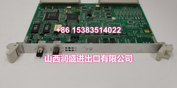
Product Core Brief
- Model: 500MBA02 / 1MRB150003R0003 / 1MRB200053/M
- Brand: ABB
- Series: ABB Drive & Power Control Systems
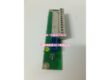
- Core Function: Control/interface board that bridges the system control backplane with power-stage or I/O sections in ABB medium-to-large drive and power control cabinets.
- Product Type: Control/Interface Board
- Key Specs: Backplane-integrated architecture | 24VDC power via backplane | Galvanic isolation | DIN rail / cabinet mounting
- Condition: New Original / New Surplus
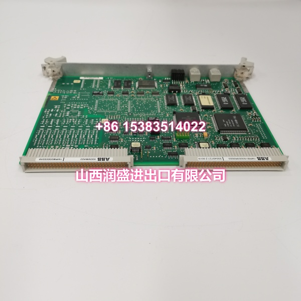
Key Technical Specifications
- Product Type: Control/Interface Board
- Brand: ABB
- Model Number: 500MBA02 / 1MRB150003R0003 / 1MRB200053/M
- Series: ABB Drive & Power Control Systems (medium-to-large drive/excitation cabinets)
- Function: Bridges the system control backplane with power-stage or I/O sections; acts as an interface layer between the drive’s main controller and peripheral subsystems.
- Power Supply: Supplied via system backplane; typically 24VDC, rated power consumption ≤8W, allowable voltage fluctuation ±10%
- Communication Interfaces: System control backplane integration; local board connectors as specified by cabinet configuration. Some variants support Modbus RTU/TCP and Profibus DP via onboard RS-485 and Ethernet interfaces with 2500V AC electrical isolation.
- Data Processing: Can handle up to 1024 input registers and 1024 output registers, supporting 32-bit data format for batch data transmission in medium/large industrial control scenarios.
- Mounting Method: Installed inside ABB drive/power-control cabinet; secured via rails or designated motherboard/backplane; DIN rail mounting compatible.
- Operating Temperature: 0°C to +55°C (cabinet ambient, ventilated); some variants rated -10°C to +60°C
- Storage Temperature: -40°C to +85°C
- Humidity: 5% to 95% (non-condensing)
- Protection Rating: IP20
- Dimensions & Weight: Approximately 120mm×80mm×60mm / 140mm×100mm×35mm (variant-dependent); weight typically under 300g
- Typical Applications: Medium-to-large ABB drive cabinets requiring backplane interface restoration; excitation systems in power generation; industrial test benches; brownfield maintenance where drive cabinet functionality must be restored without full retrofit; process lines using ABB power control systems
Product Introduction
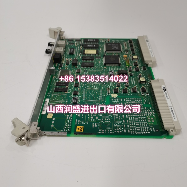
The ABB 500MBA02 (order codes 1MRB150003R0003 and 1MRB200053/M) is a control/interface board used in ABB medium-to-large drive and power control cabinets. It serves as the interface layer between the system’s control backplane and the power-stage or I/O sections, enabling the drive cabinet’s main controller to communicate with peripheral subsystems such as power modules, field I/O, and auxiliary control circuits.
This board is a critical brownfield maintenance component. When a drive or excitation cabinet faults due to interface board failure, the entire system can become inoperable — production lines, test benches, and utility processes all depend on this link being intact. The 500MBA02 is designed as a drop-in replacement, meaning swaps can be done with minimal wiring changes. Its backplane-integrated architecture reduces extra cabling and setup time, and its connector positions and labeling are consistent with ABB’s installed base, making field replacement straightforward for technicians familiar with ABB cabinet systems.
The galvanic isolation built into this class of ABB boards protects the control logic from electrical noise and transients common in drive cabinet environments. For integrators and maintenance teams managing aging ABB drive installations, this module helps extend the lifetime of existing systems without forcing a full cabinet retrofit — a significant cost saver compared to migrating to a new platform.
QA & Testing SOP
Every unit undergoes a standardized verification process before shipment:
- Visual & Anti-Counterfeit Check: Inspect the PCB for proper ABB branding, verify all identifiers (500MBA02, 1MRB150003R0003, 1MRB200053/M) match the label, and check for signs of previous installation such as edge connector wear, burnt components, or corrosion on the board surface and connector pins.
- Backplane Seating & Communication Test: Insert the board into a compatible ABB drive cabinet test rack and verify that the system controller recognizes the interface board correctly via the backplane bus, confirming proper firmware handshake and slot registration.
- Power Supply Verification: Confirm that the board draws correct current from the backplane 24VDC supply and that internal voltage regulation is within specification. Check for abnormal heat generation during powered operation.
- Interface Signal Integrity Test: Verify that all local board connectors pass signals correctly between the backplane and peripheral circuits. For variants with RS-485/Ethernet interfaces, test Modbus RTU/TCP and Profibus DP communication with appropriate isolation verification (2500V AC dielectric strength).
- Register Data Mapping Test: For variants supporting register-based data exchange, verify that input and output registers map correctly to the backplane data space, confirming no address conflicts or data corruption across the full 1024-register range.
- Anti-Static Packaging: After passing all tests, the board is placed in anti-static shielding bags with desiccant packs and rigid cardboard protection for safe transit.
Installation Pitfalls & Guide
Real-World Risks When Replacing This Board:
❗ DC Bus Discharge Wait Time: Before removing or inserting the 500MBA02, isolate all power to the drive cabinet and wait for the DC bus capacitors to fully discharge (typically 10+ minutes). Verify zero voltage at the DC bus terminals with a multimeter before proceeding. Working on a live drive cabinet risks arc flash, equipment damage, and personal injury.
❗ ESD Damage to Interface Components: This is a sensitive control interface board. Always wear an ESD wrist strap grounded to the cabinet frame when handling the board outside its anti-static packaging. Avoid touching component pins, edge connectors, or surface-mount ICs directly. Static discharge can cause latent failures that manifest weeks after installation.
❗ Backplane Connector Alignment: The board must be aligned precisely with the backplane connector guides before insertion. Forcing the board at an angle can bend backplane pins, damaging both the board and the cabinet’s motherboard. Always slide the board evenly and firmly until fully seated.
❗ Cabinet Configuration Mismatch: The 500MBA02’s local connector pinout and function depend on the specific cabinet configuration it was designed for. Installing this board in a cabinet model it was not configured for can result in incorrect signal mapping or damage to connected peripherals. Always cross-reference the cabinet type number and wiring diagram before installation.
4-Step Replacement Guide:
- Pre-Install: Isolate all power to the drive cabinet. Wait for DC bus discharge and verify zero voltage. Document existing cable connections to the board’s local connectors, note the slot position, and back up any cabinet configuration data if accessible.
- Removal: Disconnect all cables from the board’s local connectors. Release the board retention mechanism (screws or latches), and carefully slide the old board straight out of the rack. Inspect the backplane edge connector slot for bent pins or debris.
- Install: Align the new 500MBA02 with the rack guides, ensuring the keyed edge connector matches the slot orientation. Slide the board firmly and evenly into place until fully seated. Secure retention screws/latches. Reconnect all local cables according to your documented wiring.
- Power-On Test: Restore power and verify that the system controller recognizes the interface board. Check status LEDs for normal operation. Run a functional test of the drive or excitation system at low load before returning to full production.
Technical FAQ
What is the difference between order codes 1MRB150003R0003 and 1MRB200053/M? Both order codes refer to the ABB 500MBA02 control/interface board family. The different codes typically indicate variant revisions, firmware versions, or cabinet-specific configurations. When ordering a replacement, always cross-reference the order code against your cabinet’s spare parts list and the label on the original board to ensure compatibility. If your original board shows one code and the replacement shows the other, verify with the supplier that the variant is compatible with your specific cabinet model.
Can this board be used in any ABB drive cabinet? No. The 500MBA02 is designed for specific ABB medium-to-large drive and power control cabinet models. Its connector pinout, backplane interface, and firmware are configured for particular cabinet architectures. Installing it in an incompatible cabinet can result in incorrect signal mapping, communication failures, or damage to connected peripherals. Always verify cabinet model compatibility before ordering.
Does this board support hot-swapping? No. The 500MBA02 is not designed for hot-swapping. You must isolate all power to the drive cabinet and verify DC bus discharge before removing or installing the board. Hot-swapping can damage the backplane, the board, and connected power-stage components.
What symptoms indicate this board has failed? Common symptoms include: the drive cabinet failing to initialize, loss of communication between the main controller and power-stage/I/O sections, unexplained drive trips with no clear fault code, or the system controller reporting backplane communication errors. However, these symptoms can also be caused by other cabinet components (power supply, main controller, backplane itself). Always rule out power supply issues and check backplane integrity before concluding the interface board is at fault.
What warranty do you offer on New Surplus parts? We provide a full 12-month warranty on all New Original / New Surplus units. This is fundamentally different from refurbished interface boards, which often carry 30–90 day warranties and come with unknown thermal cycling history, degraded connectors, and potential firmware corruption. For a control interface board that bridges your drive cabinet’s main controller to its power stage, the reliability difference between new surplus and refurbished directly impacts system uptime and equipment safety.