Product Core Brief
- Model: IS200AEPCH1ABC
- Brand: GE (General Electric)
- Series: Speedtronic Mark VI — Power Supply Sensing Board
- Core Function: Power supply monitoring and sensing module for GE Mark VI turbine control systems, providing voltage regulation, signal processing, and system monitoring for safe and reliable steam/gas turbine operation.
- Product Type: Power Supply Sensing PCB Assembly
- Key Specs: FPGA-based processing | Auxiliary daughterboard with dual female connectors | 3 fuses, 2 terminal boards, multiple jack connectors | VME rack mount | Conductive EMI shielding | Factory-drilled mounting holes
- Condition: New Original / New Surplus
Product Introduction
The GE IS200AEPCH1ABC is a Power Supply Sensing PCB assembly from GE’s Speedtronic Mark VI turbine control series. It serves as a critical monitoring and signal processing module in the Mark VI system, which is designed to ensure the safe and reliable operation of industrial steam, gas, and hydro turbines. The board provides power supply sensing, voltage regulation, and system monitoring functions essential for turbine control system integrity.
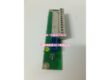
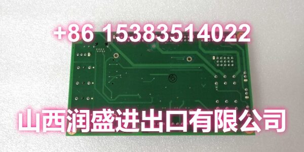
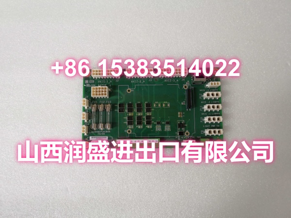
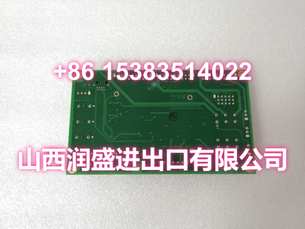
Unlike many other Mark VI boards, the IS200AEPCH1ABC is a compact rectangular card without an attached front panel. The board features factory-drilled mounting holes at each corner, each surrounded by conductive material for EMI shielding. Additional factory-drilled holes are located on the board body and along the edges for secure installation in the VME rack.
A key design feature is the auxiliary daughterboard mounted near the center of the main board surface. The daughterboard is secured to the motherboard using brackets and screws, and houses the core processing components including FPGAs, integrated circuits, dual female connectors, capacitors, resistors, diodes, and transistors. The daughterboard is marked with codes such as “DCOM” and “FA/00” for identification.
The main board surface is labeled with multiple identification codes and reference designators for component identification. Key components visible on the board include three fuses, two terminal boards, integrated circuits, and multiple jack connectors of various sizes. Two barcode labels are affixed to the board surface for inventory and tracking purposes.
The board is designed for integration into the Mark VI VME rack system and interfaces with other Mark VI boards via plug-in connectors. It plays a supporting role in the overall turbine control architecture, monitoring power supply conditions and providing feedback to the main controller for system health assessment and fault detection.
Key Technical Specifications
| Parameter | Value |
|---|---|
| Manufacturer | GE (General Electric) Energy |
| Product Family | Speedtronic Mark VI |
| Board Type | Power Supply Sensing PCB Assembly |
| Core Function | Power supply monitoring, voltage regulation, signal processing |
| Form Factor | Rectangular card, no front panel |
| Mounting | VME rack, corner mounting holes with conductive EMI shielding |
| Daughterboard | FPGA-based auxiliary board with dual female connectors |
| Fuses | 3 |
| Terminal Boards | 2 |
| Connectors | Multiple jack connectors (various sizes), dual female connectors on daughterboard |
| Daughterboard Markings | DCOM, FA/00 |
| EMI Protection | Conductive material surrounding board edges and components |
| Application | Steam, gas, and hydro turbine control systems |
| System Compatibility | GE Speedtronic Mark VI |
Quality Control Process
Every IS200AEPCH1ABC board goes through a four-stage bench check before shipping. First, a visual inspection under magnification checks for cold solder joints, cracked traces, fuse integrity, and connector pin damage — common failure points on sensing boards exposed to turbine-deck vibration and thermal cycling. We pay special attention to the daughterboard-to-motherboard interface, verifying bracket and screw integrity since mechanical fatigue at this junction is a frequent failure mode. Second, we power up the board on a verified Mark VI VME test rack and confirm all power supply sensing circuits read within spec using a Fluke 87V, verifying the three fuses are intact and the voltage regulation circuitry is functional. Third, we verify the FPGA on the daughterboard is responding correctly by checking communication through the dual female connectors, and confirm all jack connectors and terminal boards establish proper signal paths. Fourth, we confirm the board communicates correctly with the Mark VI controller via the VME backplane and verify power sensing feedback is being reported accurately to the system. Finally, the board is sealed in anti-static foam with desiccant — no exceptions.
Replacement Pitfall Guide
❗ Daughterboard-to-motherboard connection integrity. The auxiliary daughterboard is mounted to the main board via brackets and screws. Vibration and thermal cycling can cause the connectors between the two boards to loosen or the mounting screws to back out, resulting in intermittent communication or complete failure. Always inspect and re-seat the daughterboard connectors and verify all mounting screws are properly torqued during replacement.
❗ Fuse verification. The board contains three fuses that protect various power supply sensing circuits. A blown fuse will cause loss of monitoring for the associated circuit, potentially masking a power supply fault from the controller. Always test all three fuses for continuity before declaring the board functional — a board with a blown fuse may appear to work partially but will not provide complete system monitoring.
❗ VME rack slot assignment. The IS200AEPCH1ABC must be installed in the correct VME rack slot as defined by the Mark VI system configuration. Installing the board in the wrong slot can cause address conflicts and communication failures. Verify the slot assignment against the system documentation before installation.
❗ Conductive EMI shielding integrity. The board’s mounting holes and edges are surrounded by conductive material for EMI protection. If the conductive coating is damaged, corroded, or not making proper contact with the rack chassis, the board may be susceptible to electromagnetic interference from the turbine environment, causing erratic sensing readings. Inspect the conductive coating and ensure proper chassis grounding during installation.
❗ Daughterboard marking verification. The daughterboard is marked with codes such as “DCOM” and “FA/00.” If the daughterboard markings don’t match the expected revision for your Mark VI system, the board may have different firmware or hardware characteristics that are incompatible with your controller configuration. Always verify the daughterboard markings match your system requirements.
❗ Barcode and reference designator cross-check. The board has two barcode labels and multiple reference designators printed near components. Cross-check these against your system documentation to ensure you’re replacing the correct board revision. Mark VI systems can have multiple board revisions with subtle differences, and installing the wrong revision can cause compatibility issues.
Keep these in mind and you’ll cut 90% of rework time.
Compatibility Matrix & Benchmarks
| Original Model | Replacement / Successor Model | Compatibility Level | Migration Notes |
|---|---|---|---|
| IS200AEPCH1ABC (same part, new revision) | Direct | Verify daughterboard markings and firmware version | |
| IS200AEPCH1BAA | Needs Adaptation | AEPCH1BAA is a different revision; verify daughterboard configuration and fuse ratings | |
| IS200AEPCH1A | Needs Adaptation | AEPCH1A is a different revision; verify daughterboard markings and connector pinout | |
| IS215-series equivalent | Not Compatible | IS215-series boards are Mark VIe; different backplane, form factor, and communication protocol |
Benchmarks:
- FPGA-based auxiliary daughterboard with dual female connectors
- 3 fuses, 2 terminal boards, multiple jack connectors
- Conductive EMI shielding around mounting holes and board edges
- VME rack mount with factory-drilled corner mounting holes
- Daughterboard marked with DCOM and FA/00 codes
- Power supply sensing and voltage regulation for Mark VI turbine control