Product Core Brief
- Models: IS200AEPCH1ACC, IS215AEPCH1DB
- Brand: General Electric (GE)
- Series: Mark VIe (Speedtronic)
- Core Function: AEPCH (Analog I/O Processor with Channel 2 Configuration) — provides multi-channel analog signal acquisition and output for gas/steam turbine control, supporting 4-20mA, 0-10V, RTD, and thermocouple signals with ±0.1% accuracy.
- Product Type: Analog I/O Processor Module (I/O Pack)
- Key Specs: Multi-channel analog I/O | 4-20mA/0-10V/RTD/TC signal support | ±0.1% accuracy | Hot-swap capable | Dual redundant 24VDC power | Mark VIe-native backplane communication | -40°C to +70°C operating range
- Condition: New Original / New Surplus
Product Introduction
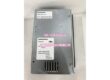
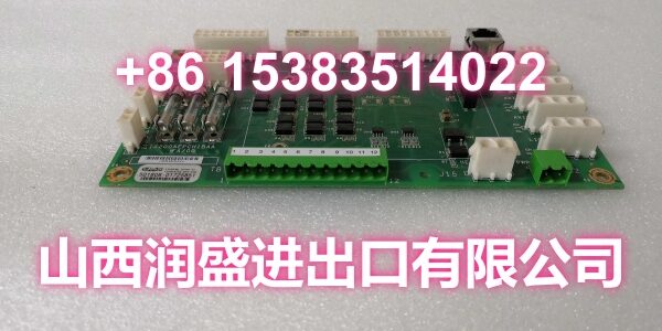
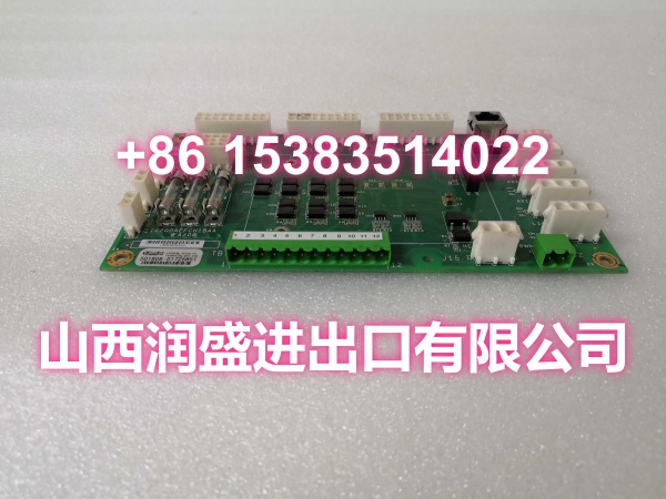
The GE IS200AEPCH1ACC and IS215AEPCH1DB are AEPCH (Analog I/O Processor with Channel 2 Configuration) modules in GE’s Mark VIe Speedtronic control system, designed for high-density analog signal processing in gas turbine, steam turbine, and combined-cycle power plant applications. These modules serve as the critical interface between field analog sensors/actuators and the Mark VIe controller, converting real-world analog signals into digital data for real-time monitoring, control logic, and safety protection functions.
The AEPCH module supports multiple analog signal types — 4-20mA current loops, 0-10V voltage signals, RTD (PT100/PT1000) temperature sensors, and thermocouple (K/J/T type) inputs — making it a versatile solution for diverse turbine monitoring needs. With ±0.1% signal accuracy, the module delivers the precision required for critical control functions such as exhaust temperature monitoring, compressor discharge pressure reading, and fuel flow control.
The IS200AEPCH1ACC and IS215AEPCH1DB integrate natively into GE’s Mark VIe control system via the proprietary backplane, communicating directly with the TCI (Turbine Control Interface) card without the protocol translation overhead associated with third-party replacements. This native integration ensures deterministic, low-latency communication between the analog I/O and the control processor — essential for fast-acting protection functions like overspeed trip and flame-out detection.
The module features hot-swap capability, allowing replacement without scheduling a full turbine shutdown. This is particularly valuable in combined-cycle power plants where an unplanned outage can cost $200,000+ per hour — technicians can simply pop the module out while the system runs (after verifying signal redundancy first) and insert the replacement without disrupting turbine operation.
Dual redundant 24VDC power inputs keep the module processing signals even if one power rail fails, providing critical protection during grid instability or brownout conditions. The redundant power paths ensure that analog I/O continues to function during the moments when it matters most — during startup, shutdown, and transient operating conditions when power quality is most likely to fluctuate.
The AEPCH module is commonly used for:
- Monitoring steam turbine exhaust temperature via RTD/thermocouple inputs
- Reading gas compressor discharge pressure for surge protection
- Monitoring lube oil pressure and temperature for bearing protection
- Driving fuel control valve positioners with 4-20mA output signals
- Reading flame detector analog signals for combustion monitoring
- Monitoring vibration and displacement sensor signals for machinery protection
- Outputting analog speed reference and load control signals
- Reading flow transmitter signals for fuel flow control and emissions compliance
The module is installed in a 3U Mark VIe chassis slot, compatible with IS200/210/215 series racks. It operates in ambient temperatures from -40°C to +70°C and is tested at 95% RH non-condensing, making it suitable for installation in I/O cabinets in power plants, refineries, and other industrial environments.
Key Technical Specifications
| Parameter | Value |
|---|---|
| Manufacturer | General Electric (GE) |
| Product Type | AEPCH Analog I/O Processor Module |
| Series | Mark VIe (Speedtronic) |
| Signal Types Supported | 4-20mA, 0-10V, RTD (PT100/PT1000), Thermocouple (K/J/T) |
| Signal Accuracy | ±0.1% of full scale |
| Power Requirements | 24VDC ±10% (dual redundant inputs) |
| Communication | Mark VIe-native backplane (TCI card interface) |
| Hot-Swap | Supported |
| Operating Temperature | -40°C to +70°C (storage: -40°C to +85°C) |
| Humidity | Up to 95% RH non-condensing |
| Installation | 3U Mark VIe chassis slot (IS200/210/215 series compatible) |
| HS Code | 8534.00.00 (Printed circuit assemblies) |
| Origin | USA |
Quality Control Process
Every IS200AEPCH1ACC and IS215AEPCH1DB goes through a full functional bench test before it ships. We start with a visual PCB inspection — checking for cold solder joints, burnt traces, swollen capacitors, and verifying the integrity of all connectors, the backplane interface, and any daughterboard connections. We also inspect the conformal coating for any cracks or peeling that could compromise environmental protection.
Then we power it up on a regulated 24VDC supply and verify the power draw is within spec. We test the dual redundant power inputs by powering the module from each input independently and confirming it operates correctly on either rail. We verify the redundant power switchover by disconnecting one input while the module is running and confirming it continues to operate without interruption.
We test all analog input channels by applying known signals — 4mA, 12mA, and 20mA for current loop inputs; 0V, 5V, and 10V for voltage inputs; simulated RTD resistance values for temperature inputs; and simulated thermocouple millivolt signals for TC inputs. We verify the input accuracy is within ±0.1% of full scale as specified. We test all analog output channels by commanding them to output specific current values and measuring the actual output with a precision multimeter, confirming accuracy within spec.
We verify the backplane communication by installing the module in a Mark VIe chassis and confirming it registers with the TCI card correctly. We test the hot-swap function by removing and reinserting the module while the chassis is powered, confirming the system detects the removal and re-insertion without faulting. We run a stability test by continuously reading all inputs and driving all outputs for several hours, monitoring for drift or communication failures. We also verify the isolation between channels by measuring resistance between adjacent channels and between channels and module ground. Finally, we confirm the module dimensions and connector alignment match the 3U Mark VIe chassis specifications. Each unit ships in anti-static foam with a moisture barrier bag.
Replacement Pitfall Guide
❗ Verify the signal type configuration matches your application. The AEPCH module supports multiple signal types (4-20mA, 0-10V, RTD, thermocouple). If the replacement module’s channel configuration doesn’t match the original (e.g., a channel configured for 4-20mA is reading an RTD signal), the controller will read incorrect values. After installing the replacement, verify the I/O configuration in ToolboxST matches your application’s I/O map.
❗ Confirm the thermocouple cold-end compensation is functioning. If your application uses thermocouple inputs, the module must perform cold-end compensation (CEC) to ensure accurate temperature readings. Verify the CEC circuit is functioning correctly after replacement — a failed CEC can cause temperature readings to drift significantly, potentially leading to false trips or missed overtemperature conditions.
❗ Don’t skip the hot-swap verification. If you’re replacing the module in a running system, verify signal redundancy first — confirm that the signals being read/output by this module are also being handled by redundant channels or modules. Removing a non-redundant module during operation could cause a turbine trip or process upset. Always coordinate with the control room before performing a hot-swap.
❗ Verify the dual power rail connections. The module has two redundant 24VDC power inputs. Ensure both are connected to independent power sources (or at least independent fuses/breakers) to provide true redundancy. If both inputs are fed from the same power source, you lose the redundancy benefit — a single power failure will take down the module.
❗ Check the backplane seating. The module communicates with the TCI card via the proprietary Mark VIe backplane. If the module is not fully seated in the chassis slot, communication may be intermittent or lost entirely. After installation, verify the module is fully seated and the backplane connector is making solid contact. Confirm the module registers on the IONet with its correct hardware ID.
❗ Watch for channel isolation degradation. The AEPCH module’s channels are electrically isolated to prevent ground loops and noise coupling between channels. If the isolation is compromised (due to damage or improper handling), signals can interfere with each other, causing erratic readings or output behavior. Verify the isolation resistance between channels meets specification before putting the module into service.
Keep these in mind and you’ll cut 90% of rework time.
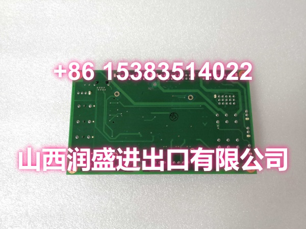
Compatibility Matrix & Benchmarks
| Original Model | Replacement / Successor Model | Compatibility Level | Migration Notes |
|---|---|---|---|
| IS200AEPCH1ACD | Direct | Later revision; verify signal type configuration match | |
| Direct | IS215 series variant; verify chassis compatibility | ||
| IS215AEPCH1DC | Direct | Later revision; drop-in compatible | |
| IS200AEPCH2CDC | Functional Equivalent | Channel 2 configuration variant; verify channel count and signal type match | |
| IS215AEPCH1FA | Functional Equivalent | FA variant; verify I/O channel configuration and firmware compatibility |
- Signal Types: 4-20mA, 0-10V, RTD (PT100/PT1000), Thermocouple (K/J/T)
- Signal Accuracy: ±0.1% of full scale
- Power: Dual redundant 24VDC inputs
- Hot-Swap: Supported
- Communication: Mark VIe-native backplane