Product Core Brief
- Model: IS220PDIOH1A
- Brand: General Electric (GE)
- Series: Mark VIe (Speedtronic)
- Core Function: PDIO (Process Discrete Input/Output) module — combines discrete input and relay output functions in a single I/O pack, supporting up to 24 contact inputs and 12 relay outputs with terminal-board-specific feedback signals.
- Product Type: PDIO Discrete I/O Module (I/O Pack)
- Key Specs: 24 discrete inputs | 12 relay outputs | Dual redundant Ethernet (IONet) | 28VDC power | TMR redundancy support | Hazardous location rated | Conformal coated
- Condition: New Original / New Surplus
Product Introduction
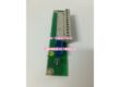
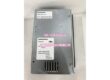
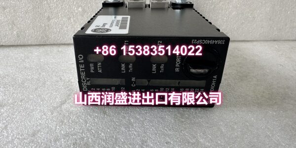
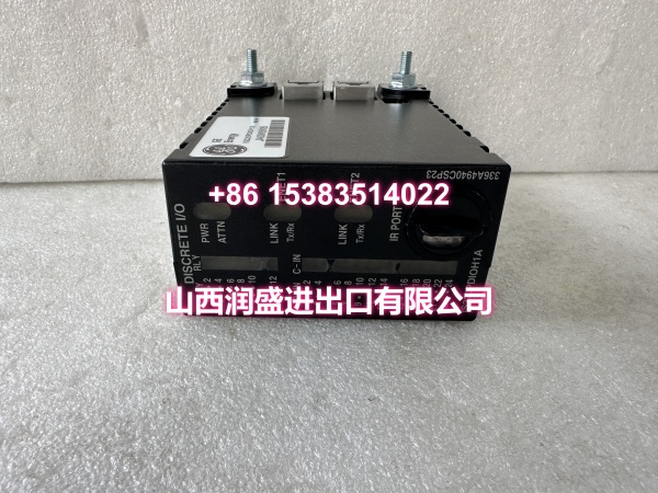
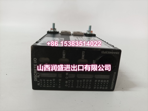
The GE IS220PDIOH1A is a PDIO (Process Discrete Input/Output) module in GE’s Mark VIe Speedtronic control system, serving as a combined discrete I/O interface for gas turbine, steam turbine, and industrial process control applications. It consolidates the functionality of both a PDIA (discrete input) and PDOA (discrete output) module into a single I/O pack, reducing rack space requirements and simplifying wiring.
The module provides up to 24 discrete contact input channels for reading field device status signals (limit switches, pressure switches, pushbuttons, relay contacts) and up to 12 relay output channels for driving field devices (solenoid valves, alarm annunciators, indicator lights, control relays). It also receives terminal-board-specific feedback signals to confirm the status of output relays and input channels.
The IS220PDIOH1A communicates with the Mark VIe processor (such as the UCSAH or UCSBH series) via dual redundant 10/100Mbps Ethernet ports (IONet), ensuring that I/O data continues to flow even if one network cable fails. The module connects to a compatible terminal board via a DC-62 pin connector, which routes the field wiring to screw terminals for easy installation and maintenance.
The module supports two terminal board configurations:
- TDBS terminal board — for simplex (single-pack) applications, combining SRLY relay output and STCI contact input functions
- TDBT terminal board — for TMR (Triple Modular Redundant) applications, combining WROB option and TBCI contact input functions
The module is approved for use in hazardous locations (Class 1, Division 2, Groups A, B, C, D) when paired with compatible terminal boards, making it suitable for installation in turbine enclosures and other areas where flammable gases or vapors may be present. Front-panel LEDs provide at-a-glance diagnostics for power, attention, and Ethernet communication status.
In turbine applications, the PDIO module is commonly used for:
- Reading turbine trip switch status, overspeed detection, and vibration switch inputs
- Driving fuel shutoff solenoid valves and lube oil pump control relays
- Activating alarm and trip annunciators
- Monitoring auxiliary equipment status (cooling fans, heaters, pumps)
- Triggering emergency shutdown (ESD) signals
Key Technical Specifications
| Parameter | Value |
|---|---|
| Manufacturer | General Electric (GE) |
| Product Type | PDIO Discrete I/O Module (I/O Pack) |
| Series | Mark VIe (Speedtronic) |
| Input Channels | Up to 24 discrete contact inputs |
| Output Channels | Up to 12 relay outputs |
| Feedback Signals | Terminal-board-specific feedback |
| Communication | Dual redundant 10/100Mbps Ethernet (RJ45, IONet) |
| Terminal Board Interface | DC-62 pin female connector |
| Power Input | 28VDC (via 3-pin power connector) |
| Redundancy | Simplex (TDBS) and TMR (TDBT) supported |
| Operating Temperature | -30°C to +65°C |
| Hazardous Rating | Class 1, Div. 2 (with compatible terminal board) |
| Conformal Coating | Yes (for harsh environment protection) |
| Certifications | CE, UL Listed, ATEX |
| Application | Turbine control I/O, relay driving, switch status monitoring, ESD signaling |
| Origin | USA |
Quality Control Process
Every IS220PDIOH1A goes through a full functional bench test before it ships. We start with a visual PCB inspection — checking for cold solder joints, burnt traces, swollen capacitors, and verifying the integrity of the DC-62 pin connector, both RJ45 Ethernet jacks, and the 3-pin power connector. We also inspect the conformal coating for any cracks or peeling that could compromise environmental protection.
Then we power it up on a regulated 28VDC supply and verify the power draw is within spec. We test each of the 24 discrete input channels by applying a known contact closure signal and confirming the module correctly reads the input state via IONet. We test each of the 12 relay output channels by commanding them ON and OFF and measuring the output voltage with a multimeter, confirming that each channel switches correctly and that the isolation between channels is intact.
We test both Ethernet ports by connecting to a network switch and confirming link/activity LEDs illuminate on each port, then verifying the module registers on the IONet with its correct hardware ID. We test the redundant communication function by disconnecting one Ethernet cable and confirming the module continues to communicate over the remaining link without data loss. We verify the TMR voting function by connecting three PDIO modules together on a TDBT terminal board and confirming they vote correctly on output states. We run a cycle test by rapidly switching each output ON/OFF for several hundred cycles, monitoring for timing jitter or output failures. We also verify the terminal-board-specific feedback signals are correctly read and reported. Finally, we confirm the module is compatible with both TDBS and TDBT terminal boards by performing a physical connection test. Each unit ships in anti-static foam with a moisture barrier bag.
Replacement Pitfall Guide
❗ Verify the terminal board compatibility before installation. The IS220PDIOH1A must be paired with either a TDBS terminal board (for simplex applications) or a TDBT terminal board (for TMR applications). Using an incompatible terminal board can result in incorrect wiring pinouts, potentially causing input signals to be misread or output signals to drive the wrong field devices — which could trigger an unintended turbine trip or fail to activate a critical safety function. Always confirm the terminal board model matches the PDIO module specification.
❗ Confirm the I/O channel configuration matches your application. The PDIO module’s input and output channels are configured in the ToolboxST software. If the replacement module’s channel configuration doesn’t match the original (e.g., different input/output assignments or different feedback signal mappings), the controller may read the wrong inputs or send commands to the wrong outputs. After installing the replacement, verify the I/O configuration in ToolboxST matches your application’s I/O map.
❗ Check the TMR voting configuration if applicable. If the PDIO module is part of a TMR arrangement on a TDBT terminal board, all three modules must be properly configured as voting members. If the replacement is configured as a simplex unit, it will not participate in the voting logic, leaving your system without I/O redundancy. Verify the TMR configuration in ToolboxST after installation.
❗ Don’t skip the input/output functional test. After installing the replacement, test each input channel by actuating the connected field device (switch, sensor) and confirming the module reads the correct state via IONet. Test each output channel by commanding it ON and verifying the connected field device (relay, solenoid, annunciator) responds correctly. A module that communicates correctly but fails to read inputs or drive outputs is a safety hazard — particularly for critical functions like turbine trip or emergency shutdown.
❗ Verify the isolation integrity. The PDIO module’s input and output isolation is critical for protecting the Mark VIe controller from field-side electrical faults. After installation, verify that there is no continuity between input channels, between output channels, and between inputs/outputs and the module ground. Compromised isolation can allow field-side voltage spikes to damage the controller or other I/O modules.
❗ Watch for Ethernet cable routing issues. The dual Ethernet ports provide redundant communication, but both cables must be routed through separate physical paths to provide true redundancy. If both cables run through the same cable tray and that tray is damaged, you lose both communication paths simultaneously. Route the primary and backup Ethernet cables through separate conduits or cable trays.
Keep these in mind and you’ll cut 90% of rework time.
Compatibility Matrix & Benchmarks
| Original Model | Replacement / Successor Model | Compatibility Level | Migration Notes |
|---|---|---|---|
| IS220PDIOH1B | Direct | Later revision; drop-in compatible | |
| (TDBS) | PDIA + PDOA separate packs | Functional Equivalent | Two separate modules replace one PDIO |
| (TDBT) | Three PDIO packs on TDBT | TMR Equivalent | Standard TMR configuration |
| IS420PDIOH1B | Needs Adaptation | Mark VIeS variant; requires I/O network migration |
- I/O Channels: Up to 24 discrete inputs + 12 relay outputs in a single pack
- Redundancy: Simplex (TDBS) and TMR (TDBT) supported
- Communication: Dual Ethernet ports for redundant IONet connectivity