Product Core Brief
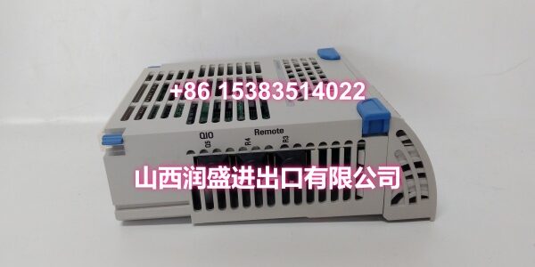
- Model: 5X00226G03
- Brand: Emerson (Ovation System, originally Westinghouse)
- Series: Ovation DCS Relay Output Subsystem
- Core Function: Relay output electronics module (E-Module) that provides electrically isolated dry-contact switching for driving solenoids, motor starters, interlocks, beacons, and audible alarms, with clean separation between control logic and field power circuits.
- Product Type: Relay Output Electronics Module (E-Module)
- Key Specs: Isolated Dry-Contact Outputs | AC/DC Load Switching | Per-Channel Status LEDs | Fail-Safe Configurable | Hot-Swappable | G03 Hardware Revision
- Condition: New Original / New Surplus
Key Technical Specifications
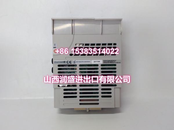
- Module Type: Relay Output Electronics Module (E-Module)
- Output Type: Dry-contact relay outputs (electrically isolated from backplane and logic)
- Load Compatibility: Switches both AC and DC loads via the same output point (actual voltage/current rating determined by the paired Personality Module relay spec)
- Channel Count: Multiple isolated relay output channels (exact count determined by PM variant)
- Status Indication: Per-channel LEDs mirror output state for quick fault tracing
- Fail-Safe Behavior: Configurable through control strategy — outputs can be set to a defined safe state on controller or communication loss
- Hardware Revision: G03 — indicates a mature component set with refined stability and lifecycle improvements versus early production runs
- Power Supply: 24VDC from the Ovation backplane (system-powered, no external logic supply needed)
- Operating Temperature: 0°C to 55°C (control room/industrial cabinet environment)
- Humidity: 5%–95% non-condensing
- Installation: DIN-rail mountable, single-slot Ovation-style module, hot-swappable
- Compatible Personality Modules (PM): High-power relay PM variants (e.g., 1C31222G01 for high-power relay output base, 1C31223G01 for G2R relay output) — PM determines the actual contact rating and channel count
Product Introduction
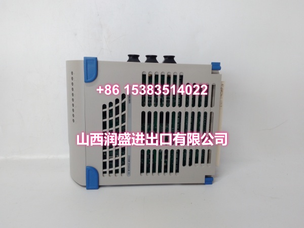
The 5X00226G03 is the electronics module (E-Module) half of Emerson Ovation’s Relay Output subsystem. It’s the go-to card when you need clean, electrically isolated switching between your DCS control logic and field devices that run on completely different power circuits — solenoid valves, motor starters, interlock relays, alarm beacons, and horn stacks.
The G03 hardware revision indicates this is a mature production run with refined component stability and lifecycle improvements over earlier revisions, making it a preferred choice for long-term MRO stocking.
What makes relay outputs different from solid-state or transistor outputs is the physical separation: the relay contacts are completely floating, meaning the field side can be 24VDC, 120VAC, or 240VAC without any electrical connection back to the controller. This isolation protects the Ovation backplane and controller from field transients, surges, and ground potential differences. The dry-contact design also means the output is agnostic to field power type — you can switch AC or DC loads on the same point, which is invaluable in brownfield retrofits where you’re inheriting mixed-voltage field wiring and don’t want to rewire the entire cabinet.
Each channel has its own status LED that mirrors the output state, so you can visually verify which relays are energized without pulling up the HMI. The fail-safe behavior is configurable in the control strategy — you can define whether outputs de-energize or hold their last state on controller loss, which is critical for safety interlock applications.
Important note: the 5X00226G03 is the E-Module only — it handles the backplane communication, logic interface, and relay coil drive. You must pair it with the correct Personality Module (PM) that provides the actual relay contacts, field-side terminal block, and surge protection. Common PM pairings include 1C31222G01 (high-power relay output base) and 1C31223G01 (G2R relay output). The modular design means you can stock E-Modules and PMs separately, reducing spare parts inventory costs.
Bottom line: if you need reliable, isolated switching for interlocks, motor controls, or alarm circuits in an Ovation installation, this is the module you spec.
QA & Testing SOP
Relay output modules are the muscle of your safety and interlock systems — if a relay fails to actuate, the consequence can be a trip or worse. Our validation protocol covers both the electronic and mechanical sides:
- Physical & Anti-Counterfeit Inspection: We verify the OEM chassis integrity, check for authentic Emerson/Westinghouse labeling and correct revision codes (confirming G03 hardware revision), and inspect the mating connector pins for corrosion or bending.
- Backplane Communication Test: The module is seated in an OEM Ovation test rack and we verify that the controller correctly reads the electronic ID from the module’s flash memory — confirming backplane communication and module identification are working.
- Per-Channel Relay Coil Drive Test: We command each output channel on and off from the controller and verify that the relay coil drive circuit activates correctly, with the corresponding LED illuminating.
- Contact Continuity & Isolation Test: With the paired PM installed, we verify that each relay contact closes and opens cleanly, and we measure the isolation resistance between the field-side contacts and the backplane to confirm electrical separation meets spec.
- Load Switching Test: We connect a representative load (resistive and inductive) to each channel and verify that the relay can make and break the load current without contact welding or excessive arcing.
- Fail-Safe Behavior Test: We simulate a controller communication loss and verify that the outputs go to their configured safe state (de-energized or held) as defined in the control strategy.
- Status LED Verification: We confirm that each channel’s LED correctly mirrors the output state in real time.
- Anti-Static Packaging: After validation, the module is sealed in industrial-grade ESD shielding bags with connector protectors installed for transit.
Installation Pitfalls & Guide
Relay output wiring mistakes can cause contact welding, false trips, or even damage to the field devices. These are the traps to avoid:
- ❗ E-Module vs. PM Confusion: The 5X00226G03 is only the E-Module — it does NOT have field wiring terminals or the actual relay contacts. You must pair it with the correct Personality Module (PM) for your load type and rating. Installing the E-Module without the PM means you have no output contacts at all. Always verify the PM part number matches your field load requirements before installation.
- ❗ Exceeding Contact Rating: The relay contacts have a maximum switching voltage and current rating determined by the PM variant. Exceeding this rating — especially with inductive loads like solenoids and motor starters — will cause contact arcing, welding, and premature failure. Always verify the load current and voltage against the PM’s contact rating, and use interposing relays if the load exceeds the direct switching capacity.
- ❗ Inductive Load Suppression: Solenoids, motor starters, and relay coils are inductive loads that generate high-voltage back-EMF when de-energized. This back-EMF can arc across the relay contacts and degrade them over time. Install flyback diodes (for DC loads) or RC snubbers (for AC loads) across the load terminals to suppress the voltage spike.
- ❗ Fail-Safe State Configuration: For safety interlock applications, the fail-safe state (what happens on controller or communication loss) must be explicitly configured in the control strategy. Don’t assume the default behavior — verify that the outputs de-energize or hold as required by your safety philosophy.
- ❗ Field Wiring Polarity (for DC Loads): While the relay contacts themselves are polarity-agnostic, the field wiring to DC loads must observe correct polarity if the load includes suppression diodes or polarized components. Double-check wiring before energizing.
- ❗ Common Mode Voltage: Although the relay contacts are isolated, the field-side wiring can still pick up common mode voltage from nearby power cables. Keep relay output wiring separated from high-voltage power cables in the cable tray, and use shielded cable where practical.
Replacement Procedure:
- Pre-Install: Back up the Ovation controller logic and I/O configuration. Document all field wiring connections on the PM terminal block. Note the slot location of the module being replaced. In the Ovation I/O Builder, set all output points on the module to “Out of Service” (Scan Off) and force them to a safe state before removal.
- Removal: Disconnect all field wiring from the PM terminal block. The Ovation system supports hot-swapping — you can remove the E-Module while the system is running, but all relay outputs on that module will de-energize during the swap. For critical interlock or motor control circuits, perform the replacement during a low-activity period or scheduled maintenance window. Open the blue locking lever, remove the E-Module, then remove the PM.
- Install: Install the new PM into the base first, then seat the new 5X00226G03 E-Module firmly into the rack slot, ensuring it mates correctly with the PM. Close the blue locking lever to secure both modules. Reconnect all field wiring per your documented terminal assignments.
- Power-On Test: The module should be recognized automatically by the Ovation controller via its electronic ID. Restore points to “In Service” (Scan On). Verify that the controller shows the module as healthy. Force-test each output channel by commanding it on and off from the controller and verifying that the relay actuates (audible click), the LED illuminates, and the field device responds correctly.
Technical FAQ
What’s the difference between 5X00226G01, 5X00226G02, and 5X00226G03? The 5X00226G01 is the electromechanical relay output module — it uses physical relay contacts for dry-contact switching, which provides complete electrical isolation and can switch both AC and DC loads. The 5X00226G02 is the solid-state relay (SSR) output module — it uses semiconductor switching with no moving parts, offering faster switching speed and unlimited mechanical life, but it’s typically DC-only and has a small voltage drop across the output. The 5X00226G03 is also a relay output E-Module (same core function as the G01) but with a G03 hardware revision — this indicates a mature component set with refined stability and lifecycle improvements over earlier production runs, making it the preferred revision for new procurement and MRO stocking.
Can I use this module without the Personality Module (PM)? No. The 5X00226G03 E-Module has no field wiring terminals and no actual relay contacts — it only connects to the Ovation backplane and mates with the PM. The PM provides the relay contacts, field-side terminal block, and surge protection. You need both to form a complete relay output channel.
What PMs are compatible with the 5X00226G03? Common compatible PMs include 1C31222G01 (high-power relay output base) and 1C31223G01 (G2R relay output). The PM determines the actual contact rating, channel count, and load type. Always verify the PM part number against your field load requirements before ordering.
Is this module hot-swappable? Yes. The Ovation system supports online module replacement. However, removing the E-Module will cause all relay outputs on that module to de-energize during the swap. For critical interlock or motor control circuits, we recommend performing the replacement during a low-activity period or scheduled maintenance window. Always set points to “Out of Service” before removal and “In Service” after installation.
How do I configure the fail-safe state for these outputs? The fail-safe state is configured in the Ovation control strategy (I/O Builder), not on the module itself. You can define whether each output point de-energizes (goes to 0) or holds its last state when the controller loses communication or goes to a fault state. For safety interlock applications, the typical configuration is de-energize-on-fail.
Do you offer volume pricing for plant MRO stocking? Yes. Relay output modules are common spare parts for any Ovation DCS installation with interlock and motor control circuits. We offer flexible pricing tiers for bulk MRO orders. Contact our sales team with your required quantity for a competitive quote.
Need the compatible Personality Module (PM) specs and the full Ovation relay output wiring diagram for this module? I can pull those up for you.