
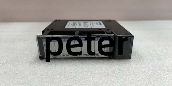
Product Core Brief
- Model:
- Brand: GE Fanuc / GE
- Series: Series 90-30 PLC
- Core Function: Operates as Genius bus master, allowing the Series 90-30 CPU to communicate with Genius remote I/O blocks, Genius controllers and field devices on the Genius serial network.
- Product Type: Genius Bus Master Communications Module
- Key Specs: Max 32 bus nodes | Software configurable baud rates | RS485 field bus interface Note: Discontinued legacy hardware; factory new stock exhausted, surplus and refurbished units widely traded. The -G suffix denotes specific PCB hardware revision. Hot swapping is not supported for Series 90-30 backplanes.
Key Technical Specifications
- Bus Mode: Genius Serial Bus Master only (Slave operation not supported)
- Supported Baud Rates: 38.4 kbps, 76.8 kbps, 153.6 kbps
- Maximum Nodes per module: 32 Genius bus devices
- Per-node data exchange: 128 bytes input / 128 bytes output
- Global broadcast data: 128 bytes transmit / 128 bytes receive
- Field Interface: Screw terminal RS485
- Required Termination: External 120Ω resistor fitted at each physical cable endpoint
- Maximum Cable Length (speed dependent): 153.6 kbps: 1066 m 38.4 kbps: 2286 m
- Backplane Power Draw: 30 mA @5 VDC
- Status LEDs: OK (module health), COM (bus activity indicator)
- Operating Temperature: 0°C to 60°C horizontal cabinet mounting
- Storage Temperature: -40°C to 85°C
- Form Factor: Single-width Series 90-30 rack slot
- Compatible Chassis: IC693CHS391, IC693CHS392, IC693CHS397, IC693CHS398
- Supported Software: Logicmaster 90, Proficy Machine Edition
Product Introduction
This unit acts as a protocol gateway between Series 90-30 CPU and legacy Genius distributed I/O systems, frequently deployed on plant retrofits with existing Genius field panels. It continuously scans all assigned Genius nodes and exchanges I/O data with the host CPU over the PLC backplane.
All network parameters, node addresses and data mapping are configured inside programming software; no hardware jumpers required for baud rate adjustment. Multiple modules can be installed within one rack to run independent, isolated Genius bus segments.
QA & Testing SOP (Transparency Building)
- Incoming Inspection: Verify part marking and -G revision suffix. Inspect backplane edge pins for bending or corrosion; check terminal block housing for cracks.
- Live Testing: Mount into validated Series 90-30 rack, apply rack power. Establish Genius bus connection with a test Genius node and run continuous 24-hour cyclic data exchange.
- Electrical Testing: Use Fluke 115 to monitor backplane rail stability. Insulation resistance testing must exceed 10MΩ between field terminals and chassis protective ground.
- Firmware/Config Backup: Record module firmware revision. Photograph field bus wiring layout before disassembly.
- Final QC & Packaging: Place unit inside anti-static shielding. Attach dated QC test tag confirming Genius bus communication validation prior to shipment.
Installation Pitfalls & Guide (Engineer to Engineer)
❗ No Hot Swap Support: Series 90-30 backplanes lack hot-swap bus logic. Live removal disrupts the entire Genius bus and risks permanent backplane damage. Full rack power shutdown mandatory. ❗ Missing Bus Termination: Absent 120Ω termination resistors at cable ends cause signal reflections, CRC errors and intermittent node dropouts. ❗ Baud Rate Consistency: All nodes on one Genius bus must use identical baud rate settings. Mismatched speeds result in zero bus traffic. ❗ Architecture Limitation: This module works exclusively on Series 90-30 racks. It cannot be installed inside RX3i main or IC694 serial expansion racks. ❗ ESD Dangers: Un-grounded handling can damage RS485 transceivers. Static faults often appear as random bus communication glitches without visible external damage. ❗ Module Revision Awareness: IC693BEM331 and are mechanically interchangeable, always perform full bus validation after cross-revision replacement.
Replacement Guide:
- Pre-install: Activate lockout-tagout on rack power; back up hardware configuration, record baud rate and Genius node address table, photograph field bus wiring.
- Removal: Disconnect Genius bus terminal wiring, unlatch module and slide straight out without twisting backplane connectors.
- Install: Seat new unit fully into vacant slot, lock latches, reattach RS485 bus wiring and fit required termination resistors.
- Power-on Test: Restore rack power, download saved configuration, confirm OK and COM LED activity; verify all Genius nodes are recognized by the CPU.
FAQ (Frequently Asked Questions)
Q: Does this module support hot swapping? A: Physically insertion is possible, but Series 90-30 backplane does not support controlled hot swap. Live removal disrupts the whole Genius bus and may trigger process faults. Planned replacement requires rack power shutdown.
Q: What is the difference between IC693BEM331 and ? A: Base number defines core Genius master functionality. The -G suffix represents a specific PCB hardware revision. Mechanically compatible, but complete bus communication testing is recommended after substitution.
Q: Can multiple modules run separate independent Genius networks? A: Yes. A single Series 90-30 rack can host multiple modules, each operating a separate Genius bus with independent wiring and node lists.
Q: Can this module be installed inside RX3i racks? A: No. Form factor and backplane signaling are exclusive to Series 90-30 chassis. RX3i systems use IC694BEM331 for Genius bus master functionality.
Q: Can this module operate as Genius bus slave? A: No. It functions only as bus master. Slave mode requires different Genius hardware.
Q: Will existing configuration download directly to a replacement module? A: Network configuration imports without modification. Always verify bus termination and baud rate after replacement to eliminate intermittent communication faults.
Q: Can Genius handheld monitors (HHM) tap onto this bus? A: Yes. A compatible Genius HHM can connect to the active bus for live diagnostics and node configuration while the CPU remains online.




