
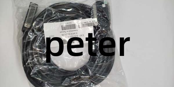
Product Core Brief
- Model:
- Brand: GE Fanuc / GE
- Series: Series 90-30 PLC
- Core Function: Wye-style shielded expansion cable interconnecting main CPU baseplate and serial expansion remote baseplates, supporting daisy-chain topology for distributed I/O racks.
- Product Type: I/O Bus Expansion Cable (Wye Type A)
- Key Specs: 25 ft (7.6 m) | 25-pin D-Sub, one single male, one male+female dual head | Continuous overall shield Note: Discontinued legacy accessory; new original stock limited, surplus and refurbished units widely traded. Supports up to 7 expansion racks per Series 90-30 CPU. Proper bus termination mandatory at the last rack in chain.
Key Technical Specifications
- Physical Length: 25 feet (7.6 meters)
- Connector Layout (Wye Type A): One end: Single 25-pin male D-Sub Opposite end: Dual-head (25-pin male + 25-pin female D-Sub) for daisy chaining
- Cable Construction: 28 AWG stranded conductors, continuous shielded cable
- Bus Interface: Series 90-30 serial I/O expansion bus (differential signal pairs)
- Maximum System Total Cable Length: 700 ft (213 m) cumulative for all expansion cables
- Supported Baseplates: IC693CHS391, IC693CHS392, IC693CHS397, IC693CHS398, IC694CHS392
- Topology Rule: Daisy-chain only; star topology is not permitted
- Termination Requirement: Install external 120Ω termination resistor on the final remote baseplate expansion port
- Operating Temperature: -20°C ~ +75°C
- Storage Temperature: -40°C ~ +85°C
- Maximum Rated Voltage: 30 VDC
- Pinout: Straight-through point-to-point differential signal wiring
- Compatibility: Works with all Series 90-30 CPUs that support serial expansion racks
Product Introduction
This cable is used to extend the serial I/O bus from the main CPU rack out to remote expansion I/O baseplates. The dual-head Wye design allows direct daisy-chaining of multiple remote racks without extra adapters.
It transports differential clock, data and control signals between racks. The full shielding suppresses industrial electromagnetic interference, critical for long cable runs between control panels. Commonly used on machine skids and field-mounted remote I/O retrofit projects with Series 90-30 systems.
QA & Testing SOP (Transparency Building)
- Incoming Inspection: Verify part marking. Inspect D-Sub shells, pin integrity, cable jacket for cuts or abrasion; check strain relief for damage.
- Live Testing: Continuity test all 25 pins; mount between validated main rack and remote baseplate. Establish serial bus communication and run 24-hour continuous I/O cyclic scanning.
- Electrical Testing: Insulation resistance testing must exceed 10MΩ between signal conductors and cable shield. Check for internal short circuits between pins.
- Documentation Check: Record cable physical condition and connector pin status. Photograph connector ends before shipment.
- Final QC & Packaging: Coil cable loosely, place inside anti-static bag. Attach dated QC test tag confirming full continuity and bus communication validation prior to shipment.
Installation Pitfalls & Guide (Engineer to Engineer)
❗ Topology Restriction: Star wiring is not supported. Only daisy-chain layout allowed. Incorrect topology causes bus collisions and intermittent remote rack dropout. ❗ Missing Bus Termination: If the farthest remote rack lacks a 120Ω terminator, signal reflections trigger CRC errors and random loss of remote I/O. ❗ Cable Model Mix-Up: (Wye dual-head) cannot be substituted directly with IC693CBL302 (single-ended terminated cable). Check connector layout before replacement. ❗ Minimum Bend Radius: Do not sharply kink the cable near strain reliefs; damaged internal conductors create intermittent communication faults. ❗ ESD Protection: Shield connections should be grounded at one end only to avoid ground loops. Do not bond shield at both rack ends. ❗ Cumulative Length Limit: Sum all expansion cables in the system; total length cannot exceed 700 ft (213 m). Exceeding this limit leads to unstable bus operation.
Replacement Guide:
- Pre-install: Lockout-tagout all rack power; record existing daisy-chain order and remote rack address DIP switch settings.
- Removal: Unplug both D-Sub connectors; carefully coil old cable and remove cable routing fasteners.
- Install: Route new cable following original path, maintain proper bend radius; connect single male end to upstream rack, dual-head male to remote baseplate input.
- Power-on Test: Restore rack power, verify all remote racks are detected by CPU in programming software; monitor for bus communication faults.
FAQ (Frequently Asked Questions)
Q: Can this cable be used on PACSystem RX3i expansion racks? A: Yes, it works for IC694CHS392 serial expansion baseplates connected to RX3i main racks with LRE001 expansion modules. Confirm serial bus architecture before use.
Q: What is the difference between and IC693CBL302? A: = 25ft Wye dual-head for daisy chaining. IC693CBL302 = 50ft single-ended terminated cable, used as the final cable at the end of a chain. They are not interchangeable for mid-chain connections.
Q: How many remote racks can be connected in one system? A: Maximum of seven serial expansion baseplates per CPU. Multiple cables can be daisy-chained to reach this limit.
Q: Can I build custom expansion cables instead of using factory IC693CBLxxx series? A: Custom wiring is permitted but must use matched differential shielded cable and correct pinout. Improper cable construction leads to unstable bus communications.
Q: Does this cable support Genius bus communications? A: No. This cable carries the Series 90-30 serial I/O expansion bus. Genius bus requires separate Genius cabling.
Q: Will a replacement cable require any PLC software configuration changes? A: No program configuration is required. After replacement, confirm all remote racks are detected and no bus fault codes exist.
Q: Can this cable be used for CPU programming communications? A: No. It is dedicated to I/O expansion bus only. Programming connections use separate serial/Ethernet ports and cables.




