
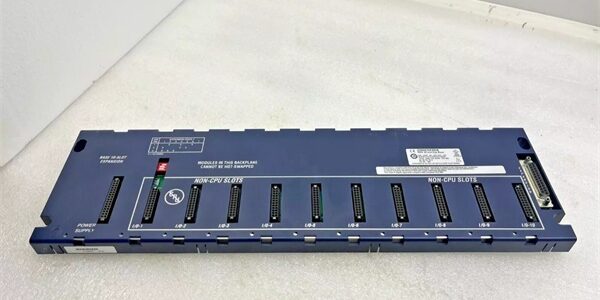
Product Core Brief
- Model:
- Brand: GE
- Series: PACSystem RX3i
- Core Function: Serial expansion backplane providing mechanical mounting, backplane power and serial bus communications for distributed remote I/O racks.
- Product Type: 10-Slot Serial Expansion Backplane
- Key Specs: 10 module slots | Serial bus only | DIP switch rack address selection Note: Discontinued hardware platform; new original stock limited, surplus and refurbished units widely traded. Leftmost slot reserved exclusively for serial expansion power supply modules. Hot swapping of modules is not supported.
Key Technical Specifications
- Total Slots: 10 slots (Slot 0 dedicated for expansion power supply; Slots 1–9 for I/O modules)
- Bus Architecture: Serial expansion bus only; no PCI bus support
- Backplane Consumption: 150 mA @5 VDC
- Compatible Power Supplies: IC694PWR321, IC694PWR330, IC694PWR331
- Max System Expansion: Up to seven serial expansion backplanes per RX3i controller
- Maximum Expansion Cable Length: 15 m (50 ft) from main rack
- Rack Identification: Onboard DIP switch for unique rack number assignment
- Operating Temperature: 0°C to 60°C horizontal cabinet mounting
- Storage Temperature: -40°C to 85°C
- Mounting: Direct subpanel mounting inside NEMA Type 1 or higher enclosure
- Supported Modules: IC694 series discrete and analog I/O modules
- Expansion Port: Right-side serial bus connector for daisy-chaining additional remote bases
Product Introduction
This unit extends PACSystem RX3i control systems by deploying remote I/O hardware away from the main controller rack. It relies on serial expansion cabling to exchange data with the host CPU via an LRE001 expansion transmitter module in the main rack.
The serial-only bus limits hardware selection to IC694 I/O modules; higher-speed IC695 PCI modules cannot be installed. This architecture is commonly used for machine skids and field-located remote I/O panels on retrofit projects.
QA & Testing SOP (Transparency Building)
- Incoming Inspection: Confirm part marking and hardware revision suffix. Inspect edge connectors for bent pins, PCB trace damage and corrosion; check mounting lugs for deformation.
- Live Testing: Install matching expansion power supply and test I/O modules. Connect serial expansion cable to validated RX3i main rack, run continuous 24-hour bus communication cycling.
- Electrical Testing: Use Fluke 115 to monitor backplane 5VDC rail stability. Insulation resistance testing must exceed 10MΩ between bus traces and chassis protective ground.
- Documentation Check: Record hardware revision. Photograph DIP switch rack address setting before any configuration changes.
- Final QC & Packaging: Place unit inside anti-static shielding. Attach dated QC test tag confirming bus communication validation prior to shipment.
Installation Pitfalls & Guide (Engineer to Engineer)
❗ No Hot Swap Support: This serial expansion backplane does not implement hot-swap logic. Removing any module under power triggers full remote rack communication failure and can damage backplane traces. ❗ DIP Switch Address Conflict: Duplicate rack numbers on multiple expansion bases cause bus collisions and intermittent loss of all remote I/O. Set rack address before powering the rack. ❗ Slot 0 Assignment Rule: Only install approved IC694 serial expansion power supplies in Slot 0. Installing I/O modules in this slot prevents backplane power distribution and bus operation. ❗ Bus Architecture Restriction: IC695 PCI-based modules will not operate on this serial backplane. Verify module catalog prefix before purchasing spare hardware. ❗ ESD Dangers: Exposed backplane connectors are sensitive to electrostatic discharge. Static damage creates intermittent communication faults that appear weeks after commissioning.
Replacement Guide:
- Pre-install: Lockout-tagout remote rack power and disconnect expansion serial cable; record rack DIP switch address and slot module layout.
- Removal: Extract all modules first; unbolt chassis from subpanel and disconnect all power wiring.
- Install: Secure new chassis horizontally, set DIP rack address to match original configuration; mount power supply in Slot 0.
- Power-on Test: Reinstall modules into matching slots, reconnect serial expansion cable, restore power and confirm all remote I/O registers in Proficy Machine Edition.
FAQ (Frequently Asked Questions)
Q: Can IC695 CPU or PCI I/O modules be installed on this backplane? A: No. This is serial-bus-only hardware. IC695 PCI modules lack serial bus signaling and will not be recognized by the controller.
Q: Does this backplane support hot swapping of I/O modules? A: No. Hot insertion or removal of any module disrupts the serial bus. Full rack power shutdown is mandatory for all module replacement.
Q: What cable connects this remote base to the main RX3i rack? A: Use IC693CBL3xx serial expansion cables. Total cable length between main rack and farthest remote base cannot exceed 15 meters.
Q: What is the difference between and IC694CHS398? A: offers 10 slots; IC694CHS398 is the 5-slot serial expansion variant. They share identical serial bus protocol and power supply compatibility.
Q: Can multiple bases be daisy-chained together? A: Yes via the right-side expansion connector. The total system limit is seven serial expansion backplanes per single RX3i controller.
Q: Will the controller report faults if the DIP rack address is misconfigured? A: Duplicate addresses trigger bus errors and partial or complete loss of remote I/O. Unique rack addressing is required for every expansion base.
Q: Can this backplane be used as a main controller rack? A: No. It lacks PCI bus and cannot host RX3i CPU modules. It functions exclusively as a remote serial expansion I/O rack.




