
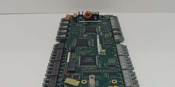
Product Core Brief
- Model: UFC760BE143, OEM article number 3BHE004573R0143
- Brand: ABB
- Series: SYNCHROTACT 5 dual-channel generator synchronizer & UNITROL excitation control rack PCB
- Core Function: Operates two fully independent generator/grid PT measuring channels to execute automatic voltage, slip and phase angle matching for dual busbar power station paralleling and synchrocheck interlocks
- Product Type: Horizontal rack-slotted dual-loop real-time excitation & synchronizing interface board
- Key Specs: Dual galvanically isolated PT inputs | SIL2 / Cat.3 PL d certified | Dual 10/100 Ethernet + Masterbus300 backplane
- Note: Full platform end-of-life; factory sealed new assemblies and fully cyclic load-tested surplus available for combined-cycle, hydro and thermal power plant cabinet maintenance
Key Technical Specifications
- Per-channel PT secondary input range: 50–130 VAC single-phase, 1500 VAC channel-to-backplane galvanic isolation
- Adjustable paralleling threshold window: Voltage difference 0.1–40%, slip frequency 0.01–6°, phase angle 1–99°
- Breaker close command latency: Fixed 10 ms core response, pulse width configurable 50–990 ms
- Communication interfaces: Dual redundant 10/100BASE-T Ethernet for SynView remote configuration, RS485 Modbus RTU, proprietary Masterbus300 rack backplane
- Auxiliary operating supply: 24 VDC ±10% SELV, max 18 W continuous power draw
- Safety compliance: IEC 61508 SIL 2, IEC 60255-127 synchrocheck standard, EU RoHS 2011/65/EU, CE certified
- Local HMI: Backlit monochrome LCD, dedicated RUN, CH1 FAULT, CH2 FAULT multi-color LED array
- Enclosure rating: IP20 for interior control cabinet mounting
- PCB surface treatment: ISA G3 conformal coating standard for coastal high-humidity substation environments
- Mechanical mounting: Standard horizontal UNITROL rack clip-in slot footprint
- Operating ambient temperature: -10°C to +60°C sealed cabinet; storage -40°C to +85°C
- Humidity tolerance: ≤75% RH non-condensing below 55°C
- Net assembly weight: 0.54 kg
- Origin: Switzerland
Product Introduction
This rack-mounted board runs two independent real-time calculation cores, sampling generator terminal PT signals and grid reference voltage to generate trim commands for excitation regulators and turbine speed governors without manual operator intervention. Dual redundant Ethernet ports eliminate single-point communication failure for remote fault waveform retrieval and site parameter adjustment, and full channel isolation prevents cross-loop voltage drift caused by unbalanced grid grounding and variable frequency drive switching transients. All control logic stores to non-volatile Flash memory to retain commissioning setpoints through full cabinet power outages.
QA & Testing SOP (Transparency Building)
- Incoming Inspection: Cross-reference serial number against ABB power protection spare asset database to filter counterfeit assemblies; inspect dual RJ45 Ethernet ports, dual PT terminal blocks, rear backplane gold edge pins and front LCD display with a 10x magnifier for pin bending, oil contamination or thermal discoloration; log serial numbers for full generator protection traceability records.
- Live Testing: Seat the unit on a standard Advant test rack paired with four independent variable AC signal simulators for dual generator and dual grid PT loops; supply rated 24VDC rack power; run a continuous 24-hour cycle test including slip deviation sweeps, phase angle window threshold validation and primary Ethernet cable pull failover simulation.
- Electrical Testing: Use a Fluke 115 insulation tester to verify ≥10MΩ isolation between each PT measuring circuit and cabinet chassis ground; measure cabinet PE continuity resistance below 0.5Ω.
- Firmware/Config Backup: Photograph front LED fault mapping and Ethernet IP DIP switch positions; record factory firmware revision printed on internal PCB silkscreen to match site existing protection logic versions.
- Final QC & Packaging: Wipe front LCD surface with static-dissipative microfiber cloth; cap Ethernet and PT terminal ports with insulating plastic dust covers; seal the unit inside a moisture-resistant shielding ESD bag, attach a printed QC tag with full 24-hour dual-channel paralleling cycle test timestamp, then pack into foam lined transit cartons.
Installation Pitfalls & Guide (Engineer to Engineer)
❗ Firmware revision mismatch disables dual-loop cross-check fault suppression: Older firmware releases lack updated slip detection algorithms; match the exact firmware version of the original hardware before power-on to avoid constant false synchrocheck fault interlocks. ❗ PT secondary wiring polarity reversal creates permanent 180° phase offset: Swapped voltage measuring leads lock the affected loop out of all paralleling window calculations until polarity correction and full rack power cycle completion. ❗ Shared ground connection for dual PT loops induces measurement drift: Each PT circuit requires independent isolated chassis grounding to eliminate cross-channel voltage offset under unbalanced grid load conditions. ❗ ESD discharge destroys internal dual-channel ADC sampling ICs: Bare finger contact with PCB measuring traces disables one or both PT input loops, requiring full unit replacement and multi-day generator outage windows during peak power demand periods. ❗ Hot-swap energized PT secondary circuits generates lethal open-circuit surge voltage: Removing the unit under live cabinet power creates high secondary open-circuit PT spikes that damage adjacent protection relays and measuring hardware in the cabinet rack.
4-step replacement guide
- Pre-install: Lock out and tag cabinet 24VDC auxiliary power supply breaker; short all PT secondary test links via dedicated test switch hardware; wait 10 minutes for internal logic capacitors to fully discharge; don ESD wrist strap; capture photos of dual PT measuring wiring, dual Ethernet cabling and Ethernet IP DIP switch layout.
- Removal: Disconnect all PT measuring wires and dual Ethernet communication cables channel by channel following captured photos; release four front panel mounting fasteners, pull the old unit straight out of the cabinet cutout without twisting rear wiring harness edge connectors.
- Install: Set DIP switches on the new hardware to match photographed IP address values; seat the unit flush against the cabinet panel to maintain IP20 internal enclosure rating; re-terminate all dual PT and Ethernet wiring matching captured polarity sequence, double-check torque fastener tightness to OEM specified values.
- Power-on Test: Restore cabinet 24VDC auxiliary power; confirm steady green RUN LED and active LCD readout for both measuring channels; inject calibrated generator/grid PT signals to validate automatic voltage/frequency trimming response; simulate primary Ethernet cable pull to confirm automatic secondary port communication failover without paralleling command interruptions.
FAQ
Q: Can this unit operate using only a single PT input channel? A: It will execute synchronization logic on the single active loop, but dual-channel cross-wiring fault detection is fully disabled. This removes a critical SIL2 safety monitoring layer and violates plant SIS operational compliance rules for dual-busbar power station designs. Q: Is hot-swapping supported while cabinet 24VDC auxiliary power and PT circuits remain energized? A: It is not supported. Live extraction creates lethal open-circuit PT secondary voltage transients and disrupts the rack’s shared Masterbus300 differential clock signals, leaving generator operation unmonitored during the replacement window. Full power lockout and PT shorting via test switches are mandatory before disassembly. Q: What warranty coverage applies to stocked units? A: Factory-new original dual-channel synchronizer interface boards carry a 12-month OEM warranty covering dual PT analog sampling circuits, redundant Ethernet transceivers, breaker close relay outputs and front LCD diagnostic arrays. Cyclic load-tested surplus units come with a 6-month functional warranty. Damage from reversed PT wiring, contaminated fiber/connector pins, ungrounded ESD handling or energized hot-swap removal voids all SIL2 certification and warranty coverage. Q: What hardware replaces this unit for new power station builds? A: New SYNCHROTACT 5 and UNITROL deployments use UFC760BE145 with expanded fault waveform recording and enhanced anti-out-of-phase detection algorithms. This variant is only approved for one-to-one maintenance replacement of pre-2024 installed dual-channel excitation synchronizing boards. Q: Will stored synchronization threshold parameters be lost after full cabinet power outage? A: All voltage deviation, slip and phase angle window setpoints save to on-board non-volatile Flash memory, so power loss does not erase site-specific commissioning tuning values. Only physical DIP switch Ethernet IP address configurations require manual matching after hardware swap. Q: What are the most common failure modes for a faulty unit? A: Persistent red FAULT LED on one or both channels with correct PT wiring sequence, failure to output trim adjustment signals to turbine/excitation control hardware, loss of automatic redundant Ethernet port failover, severe measurement drift between the two isolated PT loops, blank backlit LCD with normal 24VDC auxiliary supply, and incomplete fault waveform recording during generator paralleling transient events.




