
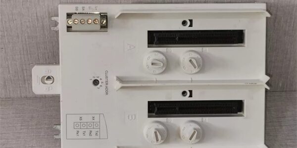
Product Core Brief
- Model: TU840 3BSE020846R1
- Brand: ABB
- Series: S800 I/O Module Termination Unit (MTU) for TB840/TB840A optical cluster modems
- Core Function: Hosts dual redundant fiber modems and distributes dual electrical ModuleBus runs for full redundant I/O clusters
- Product Type: DIN rail mounted passive module termination base
- Key Specs: Dual independent ModuleBus segments | 1–7 rotary cluster address selector | Dual 24VDC fused power inputs
- Note: Full platform end-of-life; factory sealed new assemblies and load-tested surplus available for power plant and chemical site DCS cabinet maintenance
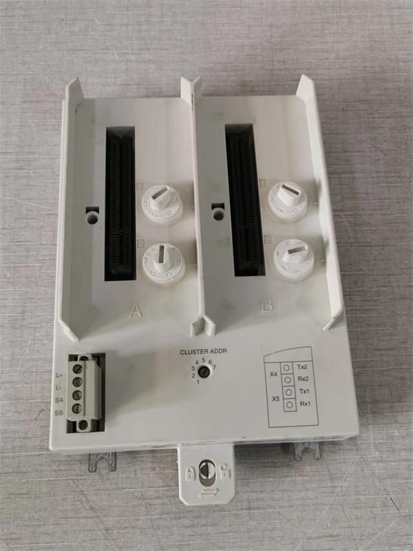
Key Technical Specifications
- OEM article number: 3BSE020846R1
- Supported modem hardware: Dual TB840 / TB840A optical ModuleBus modems
- Cluster addressing: Front rotary mechanical switch, selectable node ID 1 through 7
- Electrical bus capacity: Two isolated ModuleBus segments, max 12 I/O modules per segment
- Auxiliary power feed: Dual independent 24VDC SELV inputs with individual fuse protection
- Mechanical keying: Four configurable mechanical keys to block incompatible modem insertion
- Mounting standard: 35 mm EN 50022 DIN rail with integrated chassis grounding clip
- Enclosure rating: IP20 for interior cabinet installation
- Operating ambient temperature: -10°C to +60°C sealed cabinet; storage -40°C to +85°C
- Humidity tolerance: ≤75% RH non-condensing below 55°C
- Compliance standards: EU RoHS 2011/65/EU, IEC 60255, CE certified
- Net assembly weight: 0.45 kg
- Overall dimensions: 185 mm H × 47 mm W × 122 mm D
Product Introduction
This DIN rail base provides dedicated mounting and signal routing for paired optical media converters, splitting the ModuleBus into two isolated electrical branches to eliminate single-bus failure points for critical plant I/O clusters. Its dual fused power inputs support redundant cabinet power architectures, and mechanical keying prevents technicians from installing non-redundant modems that break SIL compliance documentation.
QA & Testing SOP (Transparency Building)
- Incoming Inspection: Cross-reference serial number against ABB S800 spare asset database to filter counterfeit assemblies; inspect dual modem slot contacts, rotary address switch and power terminal blocks with a 10x magnifier for thermal discoloration or pin corrosion; log serial numbers for full plant traceability records.
- Live Testing: Mount the base on a DIN rail test bench paired with two TB840A modems and dual 12-channel mixed analog/digital I/O load banks; supply dual 24VDC power feeds; run a continuous 24-hour cycle test including cluster address position sweeps, single power feed fault injection and full ModuleBus scan validation.
- Electrical Testing: Use a Fluke 115 insulation tester to verify ≥10MΩ isolation between ModuleBus signal terminals and cabinet chassis ground; measure PE continuity resistance below 0.5Ω.
- Firmware/Config Backup: Photograph original rotary cluster address setting and mechanical key positions from the old hardware; record OEM fuse amp rating printed on the PCB edge for site matching.
- Final QC & Packaging: Wipe plastic housing with static-dissipative microfiber cloth; cap all power and bus terminal blocks with insulating dust covers; seal the assembly inside a shielding ESD bag, attach a printed QC tag with full 24-hour redundant bus cycle test timestamp, then pack into foam lined transit cartons.
Installation Pitfalls & Guide (Engineer to Engineer)
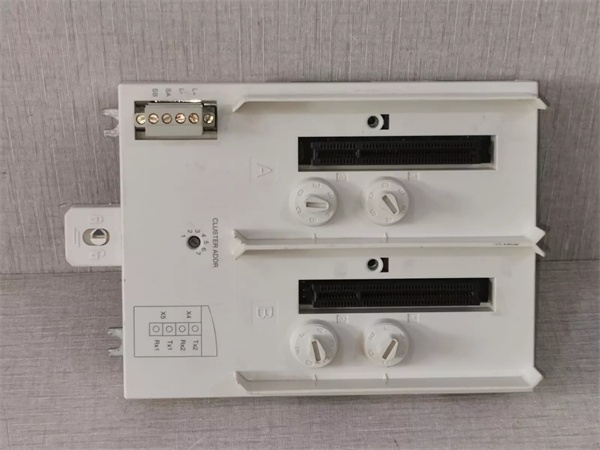
❗ Duplicate cluster address triggers mass I/O bus dropout: Photograph rotary switch positions on the old hardware before removal; matching node IDs across two bases drop all connected I/O data within 3 seconds of power restoration. ❗ Mismatched mechanical keying disables dual-bus routing: Retain photos of original key positions; wrong key settings force the unit into single-segment non-redundant mode, voiding SIL2 safety compliance. ❗ Single power feed eliminates redundant fault tolerance: Both 24VDC inputs require active supply to maintain full dual-modem failover capability; single-feed operation creates unmonitored power vulnerability windows. ❗ ESD discharge damages internal bus termination resistors: Bare finger contact with PCB signal traces can corrupt differential ModuleBus framing data, requiring full cluster power cycling to restore communication. ❗ Hot-swap energized backplane bus creates bus parity errors: Removing the base under live rack power disrupts dual ModuleBus clock signals and forces all attached I/O modules to cold restart.
4-step replacement guide
- Pre-install: Lock out and tag both cabinet 24VDC auxiliary power breakers feeding the base; wait 10 minutes for internal logic capacitors to fully discharge; don ESD wrist strap; capture photos of dual power wiring, ModuleBus cabling and original rotary address/key layout.
- Removal: Disconnect all dual power and ModuleBus wires one by one; extract both optical modems from the slots; release DIN rail retention clip, slide the old hardware horizontally off the rail without bending terminal lugs.
- Install: Set mechanical keys and rotary address switch on the new base to match photographed values; seat the unit firmly on the DIN rail; re-seat the optical modems into their dedicated slots, re-terminate all power and bus wiring to OEM specified torque values.
- Power-on Test: Restore both 24VDC auxiliary power feeds; confirm steady green RUN LED on both modems; trigger full I/O scan across both ModuleBus segments to verify zero cross-talk; simulate primary power feed loss to confirm seamless modem failover without process data gaps.
FAQ
Q: Can this base operate with only one optical modem installed? A: It will run a single bus segment, but redundant bus failover logic is disabled. This removes a critical SIL2 safety layer and violates plant documentation for dual-busbar control cabinet layouts. Q: Is hot-swapping supported while cabinet 24VDC auxiliary power remains energized? A: It is not supported. The live dual ModuleBus backplane carries high-speed differential signal frames; unplugging the base creates voltage transients that disrupt bus timing and trigger mass I/O communication failures, creating unmonitored plant process blind zones. Full power lockout and capacitor discharge wait time are mandatory. Q: What warranty coverage applies to stocked units? A: Factory-new original termination bases carry a 12-month OEM warranty covering dual ModuleBus routing circuits, rotary address switching hardware, fused power input terminals and mechanical key assemblies. Load-tested surplus units come with a 6-month functional warranty. Damage from duplicate cluster addressing, single-power-feed operation or ungrounded ESD handling voids all SIL2 certification and warranty coverage. Q: What hardware replaces this unit for new plant builds? A: New 800xA deployments integrate fiber bus conversion directly on CI867 communication interfaces, eliminating separate DIN rail modem bases. This hardware remains approved only for one-to-one maintenance replacement of legacy S800 redundant optical cluster layouts. Q: Will stored cluster address settings be lost after full cabinet power outage? A: Node ID is set via a mechanical rotary switch, so power loss does not alter cluster addressing. No firmware or custom logic data stores locally on the hardware, so no program retention functions exist. Q: What are the most common failure modes for a faulty unit? A: Persistent red FAULT LED on one modem slot with undamaged fiber cabling, loss of dual-segment ModuleBus isolation causing cross-bus signal interference, blown input fuses from over-current 24VDC supply, stuck rotary address switch unable to reassign node ID, and incomplete power telemetry upload to the DCS HMI.




