Product Core Brief
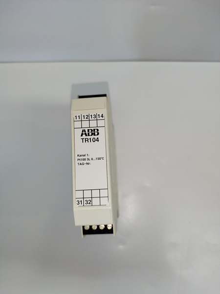
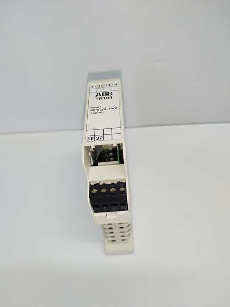
- Model: TR104
- Brand: ABB
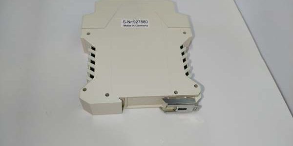
- Series: DIN rail mounted industrial temperature signal transmitter
- Core Function: Converts Pt100 RTD resistance readings to standardized 4–20mA analog loop signals for DCS/PLC I/O racks
- Product Type: Compact DIN rail RTD temperature transmitter
- Key Specs: Single channel RTD input | 4–20mA linear output | 1500VAC galvanic isolation
- Note: Active OEM spare lifecycle; factory sealed new units and calibrated load-tested surplus available for plant cooling, reactor and tank monitoring maintenance
Key Technical Specifications
- Supported sensor wiring: 2-wire, 3-wire, 4-wire Pt100 RTD
- Output signal range: 4–20mA linear analog current loop
- Measurement range: Configurable via DIP switches, -200°C to +850°C full span
- Galvanic isolation rating: 1500VAC between RTD field side and 24VDC logic supply
- Auxiliary operating supply: 24 VDC ±10% SELV, 60 mA nominal power draw
- Fault detection logic: Identifies open sensor wire, short-circuit and reversed lead wiring
- Diagnostic indicators: Single front multi-color LED for power, loop and channel fault states
- Mechanical mounting: Standard 35 mm EN 50022 DIN rail clip-in design
- Operating ambient temperature: -20°C to +70°C sealed cabinet; storage -40°C to +85°C
- Humidity tolerance: 5%–95% RH non-condensing below 55°C
- PCB coating: Standard conformal coating for mild coastal industrial environments
- Net unit weight: 0.06 kg
- Compliance standards: IEC 61000-6-2 EMC, IEC 60255, CE certified
Product Introduction
This compact DIN rail unit processes resistance changes from Pt100 temperature sensors, scaling readings into a uniform 4–20mA signal that any analog input module can read without custom scaling logic. Passive DIP switches set temperature span and wire mode on-site without PC software, and internal isolation blocks ground loop drift common across multi-section plant equipment grounding layouts.
QA & Testing SOP
- Incoming Inspection: Cross-reference serial number against ABB low voltage spare asset database to filter counterfeit assemblies; inspect RTD terminal block, front LED and PCB traces with a 10x magnifier for thermal discoloration or pin corrosion; log serial numbers for full plant asset traceability records.
- Live Testing: Mount the unit on a DIN rail test bench paired with a calibrated RTD simulator and 4–20mA analog input load bank; supply rated 24VDC auxiliary power; run a continuous 24-hour cycle test including full temperature span sweeps, wire break fault injection and cross-talk noise validation.
- Electrical Testing: Use a Fluke 115 insulation tester to verify ≥10MΩ isolation between RTD measuring terminals and DIN rail chassis ground; measure PE continuity resistance below 0.5Ω.
- Firmware/Config Backup: Photograph DIP switch span and wire mode positions; record factory calibration offset values printed on the PCB edge for field matching.
- Final QC & Packaging: Wipe plastic housing with static-dissipative microfiber cloth; cap RTD and power terminal blocks with insulating dust covers; seal the unit inside a shielding ESD bag, attach a printed QC tag with full 24-hour temperature cycle test timestamp, then pack into foam lined transit cartons.
Installation Pitfalls & Guide
❗ Mismatched DIP switch span creates permanent measurement offset: Photograph switch positions on the old hardware before removal; incorrect range settings generate false high/low temperature alarms in the DCS. ❗ Unshielded RTD cabling introduces cyclic signal noise: Cable runs longer than 10m near VFD motor drives require shielded twisted pair with single-point chassis grounding to eliminate periodic analog drift. ❗ Reversed RTD lead polarity triggers continuous fault state: Swapped sensor wires activate internal current limiting and lock the output outside the standard 4–20mA range until wiring is corrected and power cycled. ❗ ESD discharge destroys internal signal conditioning ICs: Bare finger contact with PCB measuring traces shifts calibrated output values outside ±0.1% tolerance; recalibration requires bench tooling and site downtime. ❗ Hot-swap energized 24VDC supply induces signal transients: Removing the unit under live auxiliary power creates voltage spikes that damage adjacent analog input board measuring circuits.
4-step replacement guide
- Pre-install: Lock out and tag cabinet 24VDC auxiliary control power breaker; wait 10 minutes for internal logic capacitors to fully discharge; don ESD wrist strap; capture photos of RTD field wiring and original DIP switch span/wire configuration.
- Removal: Disconnect all RTD sensor signal wires one by one; release the DIN rail retention clip, slide the old unit horizontally off the rail without bending terminal lugs.
- Install: Set DIP switches on the new hardware to match photographed span and wire mode values; seat the unit firmly onto the DIN rail; re-terminate RTD wiring following captured photos, torque terminals to OEM specified values.
- Power-on Test: Restore 24VDC auxiliary power; confirm steady green LED state; inject calibrated resistance values to verify linear 4–20mA output; simulate a broken sensor wire to confirm red fault LED activates and locks the output at under-range value.
FAQ
Q: Can this unit operate without a downstream analog input module on the DCS rack? A: It will generate a scaled 4–20mA output signal, but no process data visualization or alarm logging functions will be available. A matched analog input slave board is required to transmit temperature values to the system CPU. Q: Is hot-swapping supported while cabinet 24VDC auxiliary power remains energized? A: It is not supported. Live terminal disconnection creates voltage transients that damage the internal signal conditioning chip and can trigger over-range fault states on connected I/O modules. Full power lockout and capacitor discharge wait time are mandatory before removal. Q: What warranty coverage applies to stocked units? A: Factory-new original temperature transmitters carry a 12-month OEM warranty covering RTD measurement circuits, isolation transformers, 4–20mA output drivers and diagnostic LED hardware. Load-tested surplus units come with a 6-month functional warranty. Damage from reversed RTD wiring, unshielded field cabling or ungrounded ESD handling voids all coverage. Q: What hardware replaces this unit for new plant builds with HART communication demands? A: ABB TR204 is the upgraded variant with native HART protocol access for remote trimming and diagnostic reading. This unit remains approved only for maintenance replacement of non-HART legacy temperature monitoring loops. Q: Will stored calibration trim settings be lost after full cabinet power outage? A: Span and offset values rely on passive resistor networks on the PCB, so power loss does not alter measurement scaling. Only physical DIP switch range configurations require manual matching after hardware swap. Q: What are the most common failure modes for a faulty unit? A: Persistent red fault LED with intact RTD wiring, consistent analog output drift under cabinet temperature swings, fixed 4mA under-range reading from open isolation transformers, inability to adjust output current when sensor resistance changes, and complete loss of 4–20mA loop signal with normal 24VDC auxiliary supply.