
Product Core Brief
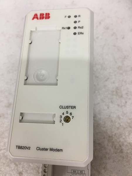
- Model: TB820V2, OEM article number 3BSE013208R1
- Brand: ABB
- Series: S800 I/O distributed rack hardware for AC800M / 800xA DCS
- Core Function: Converts electrical ModuleBus signals to fiber optic bus to extend remote I/O clusters up to 7 independent segments
- Product Type: DIN rail mounted ModuleBus optical cluster modem
- Key Specs: Dual fiber optical ports | Max 12 local I/O modules per unit | Rotary 1–7 cluster address selector
- Note: Active OEM spare lifecycle; factory sealed new units and fully load-tested surplus available for power plant, chemical and pulp mill I/O cabinet retrofits
Key Technical Specifications
- Optical bus interfaces: Dual duplex HP Versatile Link fiber ports
- Supported fiber media: POF plastic fiber (15m max), HCS hard clad silica fiber (200m max)
- Local electrical ModuleBus capacity: Up to 12 S800 I/O modules per cluster
- Cluster addressing: Front rotary switch, selectable node ID 1 through 7
- Auxiliary supply: 24 VDC ±10% SELV, 100 mA nominal power draw
- Diagnostic indicators: Front RUN, BUS, FAULT LED array for bus and power status
- PCB coating: ISA S71.04 G3 conformal coating for coastal corrosive environments
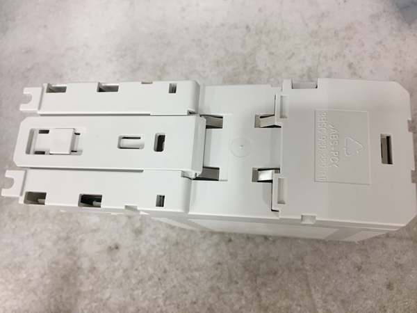
- Mechanical mounting: Standard 35 mm EN 50022 DIN rail
- Operating ambient temperature: 0°C to +55°C sealed cabinet; storage -40°C to +85°C
- Humidity rating: 5%–95% RH non-condensing below 55°C
- Enclosure rating: IP20 for interior cabinet installation
- Overall dimensions: 170 mm H × 58 mm W × 122 mm D
- Net weight: 0.3 kg
- Compliance: EU RoHS, IEC 60255, CE, ABS marine type-approved
Product Introduction
This DIN rail modem acts as a media converter between copper ModuleBus wiring and fiber optic trunk lines, eliminating EMI interference on long-distance remote I/O runs near motor control centers and variable frequency drives. Its isolated internal power supply prevents ground loop transients from disrupting I/O scanning cycles, and the rotary cluster switch enables multi-cluster plant layouts without separate communication interface modules.
QA & Testing SOP
- Incoming Inspection: Cross-reference serial number against ABB S800 spare asset database to filter counterfeit assemblies; inspect fiber transceiver ports, front rotary address switch and diagnostic LEDs with a 10x magnifier for fiber ferrule scratches or PCB thermal discoloration; log serial numbers for full I/O system traceability records.
- Live Testing: Mount the unit on a DIN rail test bench paired with a CI810 communication interface and 12-channel mixed analog/digital I/O load bank; supply rated 24VDC auxiliary power; run a continuous 24-hour cycle test including fiber cable fault injection, all 1–7 cluster address positions, full 12-module bus scan validation and fault LED trigger confirmation.
- Electrical Testing: Use a Fluke 115 insulation tester to verify ≥10MΩ isolation between fiber signal circuits and DIN rail chassis ground; measure cabinet PE continuity resistance below 0.5Ω.
- Firmware/Config Backup: Photograph rotary address switch position markings and fiber port pinout labels; record OEM maximum fiber run lengths for site wiring reference.
- Final QC & Packaging: Wipe enclosure surfaces with static-dissipative microfiber cloth; cap both fiber ports with plastic dust covers; seal the unit inside a shielding ESD bag, attach a printed QC tag with full 24-hour multi-cluster I/O test timestamp, then pack into foam lined transit cartons.
Installation Pitfalls & Guide
❗ Duplicate cluster address crashes the optical bus: Photograph the rotary switch position on the old hardware before removal; matching node IDs across two modems drop all remote I/O data within 3 seconds of power restoration. ❗ Dirty fiber ferrules create permanent packet loss: Oil residue from bare finger contact blocks light transmission; clean fiber tips with OEM alcohol wipes before plugging into the ports. ❗ Exceeding maximum fiber run length increases scan delay: HCS fiber runs longer than 200m introduce scan cycle lag above 250ms, breaking closed-loop control timing windows. ❗ ESD discharge destroys optical transceiver ICs: Static contact with PCB fiber circuits disables both optical ports; replacement hardware and associated production downtime exceed $8,000 for large power station I/O clusters. ❗ Hot-swap energized 24VDC supply corrupts bus framing data: Removing the unit under live auxiliary power forces all connected I/O modules to cold restart, creating a plant monitoring blind zone.
4-step replacement guide
- Pre-install: Lock out and tag cabinet 24VDC auxiliary power supply; wait 10 minutes for internal logic capacitors to fully discharge; don ESD wrist strap; capture photos of duplex fiber cabling and original rotary cluster address setting.
- Removal: Unplug both fiber optic cables from front transceiver ports; release the DIN rail retention clip, slide the unit horizontally off the rail without bending fiber ferrules.
- Install: Set the rotary address switch on the new hardware to match photographed values; clip the unit firmly onto the DIN rail; re-seat cleaned fiber cables straight into the dual optical ports to avoid ferrule scratching.
- Power-on Test: Restore 24VDC auxiliary power; confirm steady green RUN LED; trigger full I/O scan across all 12 local modules and remote fiber-connected clusters; simulate fiber cable pull to confirm red FAULT LED activates and logs the bus fault to the DCS HMI.
FAQ
Q: Can this unit operate without fiber optic cabling connected? A: It will communicate with the local 12-module copper I/O cluster, but all remote fiber-connected I/O segments remain offline. The fiber ports are required for multi-cluster distributed I/O layouts. Q: Is hot-swapping supported while cabinet 24VDC auxiliary power remains energized? A: It is not supported. Live removal disrupts the electrical ModuleBus clock signals and triggers mass I/O communication failures, which disable process monitoring loops. Full power lockout and capacitor discharge wait time are mandatory. Q: What warranty coverage applies to stocked units? A: Factory-new original optical cluster modems carry a 12-month OEM warranty covering dual fiber transceivers, isolated power supply circuits, rotary address switching hardware and diagnostic LED arrays. Load-tested surplus units come with a 6-month functional warranty. Damage from contaminated fiber ferrules, duplicate cluster addressing or ungrounded ESD handling voids all coverage. Q: What hardware replaces this unit for new plant builds? A: New 800xA deployments use CI867 fiber-enabled communication interfaces that eliminate separate cluster modems. This unit remains approved only for one-to-one maintenance replacement of legacy S800 multi-cluster I/O systems. Q: Will stored cluster address settings be lost after full cabinet power outage? A: Node ID is set via a mechanical rotary switch, so power loss does not alter the cluster address. No firmware or control logic data stores locally on the hardware, so no program retention functions exist. Q: What are the most common failure modes for a faulty unit? A: Persistent red FAULT LED with undamaged fiber cabling, one-way fiber transmission with zero receive data, full loss of communication to all remote I/O clusters, inconsistent scan timing under maximum 12-module local load, and failure to detect fiber cable breakage events for fault logging.




