
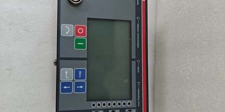
Product Core Brief
- Model: 1VCF750090R804
- Brand: ABB
- Series: HSTS High Speed Transfer System medium voltage power switching control
- Core Function: Front door-mounted HMI panel for local configuration, status monitoring and manual transfer commands for bus transfer protection logic
- Product Type: IP54 rated door mount operator touch panel assembly
- Key Specs: Resistive TFT LCD | Front optical service port | Multi-protocol backend comms interface
- Note: Active lifecycle OEM spare; factory sealed new units and bench-tested surplus available for refinery, power plant MV switchgear retrofits
Key Technical Specifications
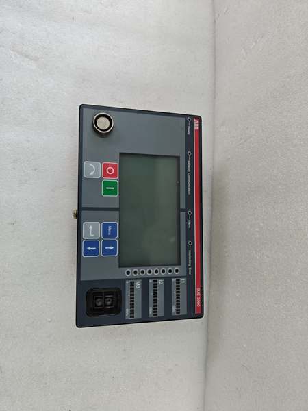
- Display: Color resistive TFT LCD with backlight, multi-language support
- Front rating: IP54 dust/water splash protection for cabinet door mounting
- Local interface: Tactile physical navigation buttons + touch input
- Service port: Front optical isolated port for PC configuration via FUPLA software
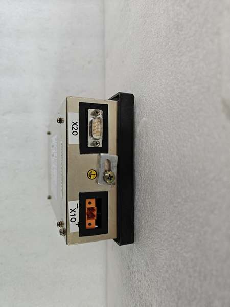
- Backend communication: Ethernet IEC 61850, Modbus RTU, SPA bus, Profibus DP
- Auxiliary supply: 24VDC ±10% SELV control power, 12W nominal draw
- Status indicators: Programmable multi-color LED array for feeder, breaker and fault states
- Mount cutout: Standard MV cabinet door cutout footprint for direct drop-in swap
- Operating temperature: -10°C to +70°C inside sealed switchgear compartments
- Storage temperature: -40°C to +85°C
- Humidity tolerance: 20%–95% RH non-condensing below 55°C
- Mechanical dimensions: 240mm H × 185mm W × 42mm D
- Net weight: 0.65kg
- Compliance: IEC 61850, IEC 60255, CE certified
Product Introduction
This door-mounted panel acts as the local human interface for the high speed transfer core unit, letting field technicians view feeder voltage, breaker position and transfer fault records without remote SCADA access. Its isolated optical front port eliminates galvanic coupling risks during on-site logic edits, and preprogrammed LED mapping visualizes 30ms inter-feeder transfer events for critical motor and process loads.
QA & Testing SOP (Transparency Building)
- Incoming Inspection: Cross-reference serial number against ABB MV spare asset database to reject counterfeit assemblies; inspect LCD panel, optical port and front tactile buttons with a 10x magnifier for scratch damage or backlight failure; log serial numbers for substation traceability records.
- Live Testing: Mate the panel to a full core test rack with VM1-T vacuum breaker simulation; supply rated 24VDC auxiliary power; run a continuous 24-hour cycle test including manual transfer trigger, fault record playback and FUPLA configuration upload via optical port.
- Electrical Testing: Use a Fluke 115 insulation tester to verify ≥10MΩ isolation between front optical service port and backend communication wiring; confirm cabinet PE chassis continuity below 0.5Ω.
- Firmware/Config Backup: Photograph LED status mapping and optical port pinout; record factory firmware revision printed on internal PCB silkscreen to match site existing core unit firmware.
- Final QC & Packaging: Wipe front panel surface with static-dissipative microfiber cloth; cap optical port and backend communication connectors with insulating dust covers; seal the assembly inside a shielding ESD bag, attach a printed QC tag with full 24-hour transfer cycle test timestamp, then pack into foam lined transit cartons.
Installation Pitfalls & Guide
❗ Firmware version mismatch blocks transfer command execution: Mismatched HMI and core unit firmware disables manual bus switching; match exact revision numbers before power-on to avoid unprotected load outages. ❗ Cabinet door gasket gaps break IP54 rating: Improperly seated panel creates moisture ingress, which corrodes internal LCD backlight circuits within 6 months of coastal site operation. ❗ Unshielded backend Ethernet cabling causes IEC 61850 packet loss: Cable runs longer than 10m without shielded twisted pair generate constant comms retries during breaker switching transients. ❗ ESD discharge destroys optical transceiver ICs: Bare finger contact with internal PCB traces can disable the service port, requiring full unit replacement and 4+ hour site downtime. ❗ Hot-swap energized 24VDC supply corrupts transfer event logs: Removing the panel under live auxiliary power erases stored disturbance recorder fault history with no recovery method.
4-step replacement guide
- Pre-install: Lock out and tag the MV cabinet 24VDC auxiliary control power breaker; wait 10 minutes for internal logic capacitors to fully discharge; don ESD wrist strap; capture photos of backend communication wiring and door mounting gasket alignment.
- Removal: Disconnect all rear Ethernet/serial comms cables one by one; unfasten four corner mounting screws, pull the old unit straight out of the door cutout without twisting the flat ribbon internal wiring.
- Install: Seat the new panel flush against the cabinet door gasket to maintain IP54 rating; secure mounting screws to OEM torque values; re-terminate all backend communication wiring matching photographed routing.
- Power-on Test: Restore 24VDC auxiliary power; confirm backlit LCD activates and all status LEDs cycle normally; connect a laptop via the front optical port to upload a test FUPLA logic file; trigger a manual transfer sequence to verify breaker command signals send to the core unit without comms dropout.
FAQ
Q: Can this panel operate standalone without a core transfer unit? A: No. The device only serves as a visualization and command input terminal; all voltage measurement, phase sync and breaker trip logic resides on the central core unit. Without a paired core, the touch panel will display only a blank fault screen with no controllable functions. Q: Is hot-swapping supported while cabinet 24VDC auxiliary power remains energized? A: It is not supported. Live disconnection creates voltage transients on the backend communication bus that corrupt stored disturbance recorder data and force the central transfer core unit to cold restart, creating a window of unprotected critical process loads. Full power lockout and capacitor discharge wait time are mandatory. Q: What warranty coverage applies to stocked units? A: Factory-new original HMI panels carry a 12-month OEM warranty covering the LCD backlight, optical service port transceivers, touch input circuits and diagnostic LED arrays. Bench-tested surplus units come with a 6-month functional warranty. Damage from gasket misalignment moisture ingress, mismatched firmware or ungrounded ESD handling voids all coverage. Q: What hardware replaces this unit for new MV switchgear builds? A: New system deployments use the updated 1VCF750090R0805 variant with capacitive touch and built-in webserver access. Legacy 1VCF750090R804 remains approved only for one-to-one replacement of existing pre-2020 transfer systems. Q: Will stored disturbance fault records be retained after panel replacement? A: All transfer event logs and fault waveforms store on the central core unit’s non-volatile memory, so swapping the HMI does not erase historical data. Only local touchscreen display customizations (LED mapping, screen layout) require reconfiguration post-install. Q: What are the most common failure modes for a faulty unit? A: Dim or non-functional LCD backlight under normal 24VDC supply, unresponsive touch input on half the display area, optical service port unable to establish PC connection, intermittent loss of Modbus/IEC 61850 backend communication, and failure to log manual transfer trigger events to the core unit recorder.




