
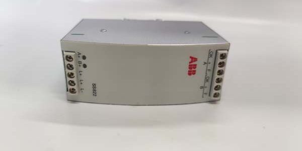
Product Core Brief
- Model: SS822 3BSC610042R1
- Brand: ABB
- Series: System 800xA / AC800M S800 I/O redundant power management hardware
- Core Function: Combines two separate 24VDC power feeds into a single supervised output for control rack loads
- Product Type: DIN rail mounted diode power voting unit
- Key Specs: Dual 24–28VDC inputs | 20A max continuous output | <50ms automatic failover
- Note: Active OEM lifecycle; factory sealed new units and load-tested surplus available for SIS and standard DCS cabinet upgrades
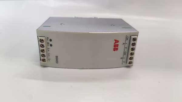
Key Technical Specifications
- Input voltage range: 24 VDC to 28 VDC SELV/PELV
- Input channel count: 2 independent isolated DC power inputs
- Rated continuous output current: 20 A; 25 A peak for 10 second transient loads
- Transfer switching time: <50 ms between primary and backup power source
- Max power dissipation: 6 W at full rated load
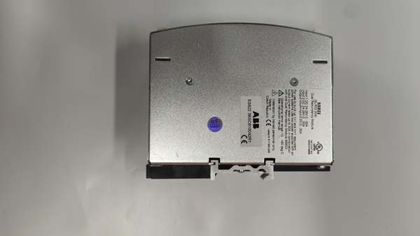
- Mechanical mounting: 35 mm standard EN 50022 DIN rail
- Diagnostic indicators: Front green LED per input channel, common OK status output relay contact
- PCB coating: ISA S71.04 G2 standard conformal coating; G3 coated variant SS822Z available for corrosive environments
- Operating ambient temperature: -25°C to +70°C sealed cabinet
- Storage temperature range: -40°C to +85°C
- Humidity rating: 20%–95% RH non-condensing below 55°C
- Safety certifications: CE, UL 508, CSA; IEC 61508 SIL2 capable when paired with SD83x power supplies
- Overall dimensions (W × H × D): 50 mm × 108 mm × 132 mm
- Net unit weight: 0.8 kg
Product Introduction
This DIN rail hardware uses high-current power diodes to create a redundant 24VDC supply for S800 I/O racks, AC800M controllers and SIS safety hardware. It continuously monitors voltage levels on both input legs and switches loads to the healthy source without program intervention. Its fixed under-voltage trip thresholds prevent undervoltage transients from triggering controller cold restarts, and the dry contact OK signal provides remote power health telemetry to plant SCADA servers.
QA & Testing SOP
- Incoming Inspection: Cross-reference serial number against ABB OEM spare database to filter counterfeit assemblies; inspect terminal screw lugs, front diagnostic LEDs and conformal coating with a 10x magnifier for thermal discoloration or cracked solder joints; log serial numbers for full SIS traceability records.
- Live Testing: Mount the unit on a DIN rail test bench paired with dual SD833 20A power supplies; connect a resistive 20A load bank matching full rack draw; run a continuous 24-hour cycle test including forced input power dropouts to validate <50ms failover timing and status relay operation.
- Electrical Testing: Use a Fluke 115 insulation tester to verify ≥10MΩ isolation between input power terminals and DIN rail chassis ground; measure PE continuity resistance below 0.5Ω.
- Firmware/Config Backup: Photograph front LED channel mapping and factory voltage trip threshold labels printed on the PCB; record model coating grade (G2 or G3 SS822Z) for site environmental matching.
- Final QC & Packaging: Wipe PCB surfaces with static-dissipative microfiber cloth; cap all DC input/output terminal blocks with insulating dust covers; seal the unit inside a shielding ESD bag, attach a printed QC tag with full 24-hour load cycle test timestamp, then pack into foam lined transit cartons.
Installation Pitfalls & Guide
❗ Mismatched power supply current ratings create overload: Pairing 10A SD832 supplies with this unit creates permanent current limiting; both feed sources must carry 20A rated output capacity. ❗ Reverse DC input polarity burns internal power diodes: No reverse blocking circuitry on input terminals; miswiring one feed leg destroys the voting diode stack instantly. ❗ Unsecured DIN rail mounting causes thermal drift: Loose hardware creates poor heat dissipation, raising internal diode temperature and triggering premature under-voltage trips under full load. ❗ ESD contact degrades voltage monitoring ICs: Bare finger contact with PCB sensing traces shifts trip thresholds outside factory calibration ranges, requiring full bench recalibration before deployment. ❗ Hot-swap energized DC feeds creates arc flash hazards: Disconnecting live 24VDC power lugs while the unit carries 20A load generates sustained arcs that damage terminal lugs and nearby control wiring.
4-step replacement guide
- Pre-install: Lock out and tag both primary and backup 24VDC power supply breakers; wait 10 minutes for power supply output capacitors to fully discharge; don ESD wrist strap; capture photos of dual input DC wiring and OK status relay field cabling.
- Removal: Loosen all input/output terminal screws one by one; slide the unit horizontally off the DIN rail without bending terminal lugs.
- Install: Seat the new unit firmly on the DIN rail and lock the retention clip; re-terminate dual DC input and load output wiring with OEM specified torque values, confirm polarity matches photographed routing.
- Power-on Test: Restore both 24VDC power feeds; confirm both green input LEDs illuminate; simulate primary power feed loss to verify <50ms failover and active OK relay contact state; run full rack load for 1 hour to check for abnormal chassis heating.
FAQ
Q: Can this unit operate with only one DC power input connected? A: It will supply power to the rack load from the single active feed, but all redundant fault tolerance is lost. The SCADA OK relay contact remains closed, masking the single-source power vulnerability from plant operators. Dual powered inputs are required for SIL2 safety compliance. Q: Is hot-swapping supported while DC power feeds remain energized? A: It is not supported. Live terminal disconnection creates DC arcs and voltage transients that can damage the internal diode stack and downstream controller CPU logic. Full lockout of both upstream power breakers and capacitor discharge wait time are mandatory. Q: What warranty coverage applies to stocked units? A: Factory-new original power voting units carry a 12-month OEM warranty covering high-current diodes, voltage monitoring circuits and status relay contacts. Load-tested surplus units come with a 6-month functional warranty. Damage from reversed DC polarity, mismatched under-rated power supplies or ungrounded ESD handling voids all coverage and SIL2 certification validity. Q: What hardware replaces this unit for new high-corrosion cabinet builds? A: The SS822Z G3 conformal coated variant is the direct drop-in replacement for coastal, chemical and offshore sites. For full new DCS builds with higher safety demands, ABB specifies SS823 dual-voter hardware with dual overvoltage protection circuits. Q: Will factory voltage trip thresholds shift after a full cabinet power outage? A: Trip levels are set via passive resistor networks on the PCB, so power loss does not alter under/overvoltage trigger points. Only physical DC wiring polarity and DIN rail mounting torque require inspection after hardware replacement. Q: What are the most common failure modes for a faulty unit? A: Permanent loss of one input channel from burned power diodes, failover timing exceeding 100ms leading to controller cold restarts, stuck open OK status relay contact with active dual power feeds, excessive chassis heating under rated 20A load, and voltage monitoring offset causing false power fault alarms on SCADA.
ABB 的应用领域有哪些?
ABB 的市场价格是多少?
ABB 的详细技术参数有哪些?




