Product Core Brief
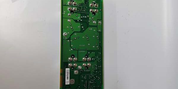
- Model: SR511 3BSE000863R0001
- Brand: ABB
- Series: S800 I/O Safety Instrumented System (SIS) rack module for AC800M / 800xA DCS
- Core Function: Provides certified safety-rated relay outputs for emergency shutdown, machine guard and fire/gas interlock circuits
- Product Type: Rack-slotted SIL2 safety relay output module
- Key Specs: 4 dual-channel safety relay outputs | SIL2 / Cat.3 PL d certified | Profibus DP communication
- Note: Still active OEM production; factory sealed new units and fully load-tested surplus available for plant SIS maintenance and expansion
Key Technical Specifications
- Safety Certification: IEC 61508 SIL 2, EN ISO 13849-1 Category 3, PL d
- Output Channels: 4 independent dual-channel safety relay contacts (NO/NC)
- Contact Rating: 250VAC / 6A resistive load per channel
- Fieldbus Interface: Profibus DP, 9.6k–12M baud auto-detect
- Logic Supply: 24VDC ±10% SELV from S800 rack backplane, 4W nominal draw
- Memory: Non-volatile Flash stores safety channel configuration, no backup battery needed
- Diagnostic Indicators: Front RUN, BUS, CHx FAULT LEDs for each safety loop
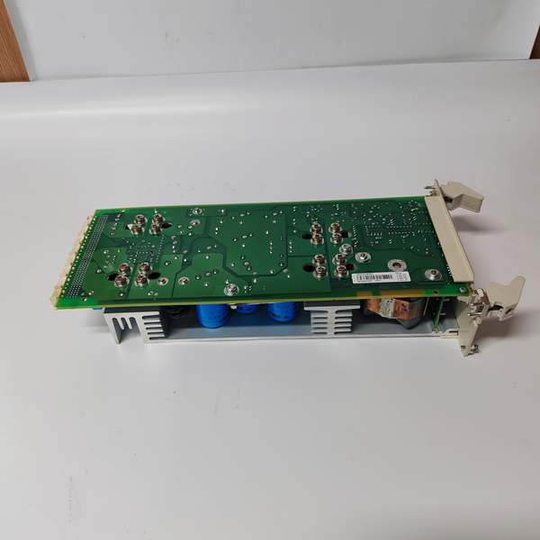
- PCB Protection: Standard ISA G3 conformal coating for humid, coastal industrial cabinets
- Operating Ambient Temp: -10°C to +60°C sealed cabinet; storage -40°C to +85°C
- Humidity Tolerance: ≤75% RH non-condensing
- Isolation Rating: 2500VAC between field safety contacts and backplane logic circuits
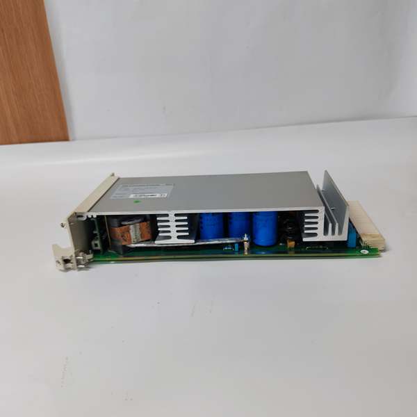
- Mechanical Fit: Standard S800 I/O rack slot, compatible with TU810/TU811 terminal bases
Product Introduction
This unit mounts to S800 terminal bases to execute hardwired safety trip logic independent of standard process control, sending relay signals to ESD valves, motor shutdown circuits and safety isolation breakers. Its dual-channel cross-monitoring circuit detects relay contact welding or open wiring faults, triggering immediate fault alarms before unsafe equipment operation can occur.
QA & Testing SOP
- Incoming Inspection: Cross-reference serial number against ABB OEM spare database to filter counterfeit assemblies; inspect Profibus connector, front diagnostic LEDs and relay terminal blocks with a 10x magnifier for contact burn marks or coating damage; log serial numbers for full SIS traceability records.
- Live Testing: Seat the unit on a TU811 terminal base paired with a PM866 controller; wire 4-channel resistive load banks matching rated contact capacity; run a continuous 24-hour cycle test including forced contact fault injection to validate cross-channel monitoring and fault LED triggers.
- Electrical Testing: Use a Fluke 115 insulation tester to verify ≥10MΩ isolation between safety contact terminals and rack ground; measure chassis PE continuity to confirm resistance below 0.5Ω.
- Firmware/Config Backup: Photograph front LED fault mapping and Profibus address DIP switch positions; record exact factory firmware revision printed on PCB silkscreen for site firmware matching.
- Final QC & Packaging: Wipe PCB surfaces with static-dissipative microfiber cloth; cap Profibus port and field terminal blocks with insulating dust covers; seal the unit inside a shielding ESD bag, attach a printed QC tag with full 24-hour safety loop test timestamp, then pack into foam lined transit cartons.
Installation Pitfalls & Guide
❗ Firmware revision mismatch disables SIL fault diagnostics: Older firmware builds lack dual-contact cross-check logic; match the exact firmware version of the existing safety module before power-on to avoid invalidating SIL2 certification. ❗ DIP switch address duplication causes Profibus bus collision: Photograph DIP switch positions on the old hardware before removal; duplicate Profibus node IDs drop all SIS communication within 5 seconds of rack power restoration. ❗ Single-channel wiring defeats Category 3 safety rating: Do not jumper dual-channel safety contacts together; single-path wiring removes fault detection and voids plant safety compliance documentation. ❗ ESD contact ruins safety relay monitoring ICs: Bare finger contact with PCB logic traces can disable cross-channel fault detection; replacing this unit requires full SIS re-validation, costing multiple days of production downtime. ❗ Hot-swap energizes unmonitored safety circuits: Pulling the module under live rack power opens critical ESD interlock paths and creates unprotected safety blind zones for the plant.
4-step replacement guide
- Pre-install: Lock out and tag rack 24VDC auxiliary power; wait 10 minutes for internal capacitors to fully discharge; don ESD wrist strap; capture photos of Profibus cabling, safety contact field wiring and Profibus address DIP switch layout.
- Removal: Disconnect all field safety loop wires and Profibus cable one by one; release the front rack latch, slide the old unit straight out of the TU811 base without bending contact pins.
- Install: Set DIP switches on the new hardware to match photographed address values; align the board with terminal base rails and seat fully until the latch clicks locked; re-terminate all dual-channel safety wiring with OEM specified torque values.
- Power-on Test: Restore rack 24VDC power; confirm steady green RUN LED; cycle each safety output channel 100 times to verify consistent relay actuation; simulate a welded contact fault to confirm channel FAULT LED activates and sends fault alarms to the 800xA SIS HMI.
FAQ
Q: Can this unit operate without a PM8xx series controller? A: No. The module relies on Profibus DP to exchange safety program logic and fault event data with a safety-certified CPU. Without a matched controller, all safety interlock monitoring and relay control functions remain offline. Q: Is hot-swapping supported while rack power remains energized? A: It is not supported. Live extraction opens active safety output circuits and removes cross-monitoring fault detection, creating an unprotected safety blind zone that violates SIL2 operational requirements. Full power lockout and capacitor discharge wait time are mandatory. Q: What warranty coverage applies to stocked units? A: Factory-new original safety relay modules carry a 12-month OEM warranty covering dual-channel monitoring circuits, relay contact assemblies and Profibus communication transceivers. Load-tested surplus units come with a 6-month functional warranty. Damage from single-channel safety wiring, mismatched firmware or ungrounded ESD handling voids all coverage and safety certification validity. Q: What hardware replaces this unit for new SIS projects? A: New 800xA safety systems use SR513 upgraded safety output modules with extended contact ratings and native Profisafe support. remains approved only for maintenance replacement of legacy SIS racks. Q: Will stored safety channel configuration be lost after a full rack power outage? A: Safety loop parameter sets save to on-board Flash memory, so power loss does not erase channel enable or fault threshold settings. Only physical DIP switch Profibus node IDs require manual matching after hardware replacement. Q: What are the most common failure modes for a faulty unit? A: Persistent channel FAULT LED with intact field wiring, one relay contact stuck closed (welded contact failure), loss of cross-channel fault monitoring logic, intermittent Profibus DP communication drops under normal load, and failure to trigger ESD shutdown commands during safety loop fault conditions.