
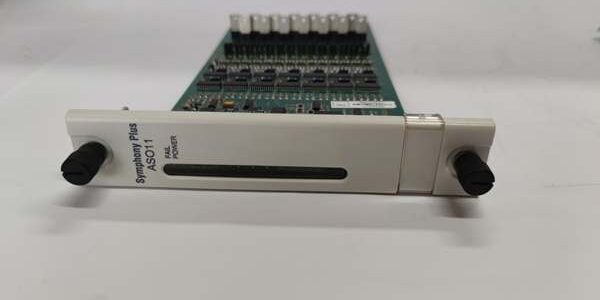
Product Core Brief
- Model: SPASO11
- Brand: ABB Hitachi Energy (Bailey Legacy Series)
- Series: Symphony Plus / Bailey Infi 90 distributed control system rack-slotted analog output slave module
- Core Function: A high-density analog output slave board that converts digital control commands from the Symphony Plus master controller into standardized analog control signals to drive field actuators: control valves, variable frequency drives, positioners, and local indicating meters. It features 14 independent output channels with group galvanic isolation, supporting standard 4–20mA current loop and 1–5VDC voltage output. It communicates via the proprietary Symphony backplane bus to exchange setpoint values, fault status and loop diagnostic data with the master CPU. Built-in hardware protection prevents module and field actuator damage from short-circuit, overcurrent and reverse polarity miswiring. Conformal PCB coating enables stable operation in high-humidity, corrosive industrial and coastal power plant control rooms.
- Product Type: Rack-mounted analog output slave PCB for Symphony Plus DCS
- Key Specs: 14 isolated analog output channels; signal types 4–20mA / 1–5VDC; 12-bit D/A conversion resolution; group galvanic isolation between field output loops and rack backplane logic bus; built-in channel overcurrent limiting, short-circuit auto-recovery shutdown, reverse input polarity protection; powered via rack backplane 24VDC logic supply; dedicated Symphony rack slot installation; front POWER / FAIL diagnostic LED indicators; ISA G3 anti-corrosion conformal coating; backward compatible with IMASO11 older generation output modules
- Note: The entire Symphony Plus Bailey Infi 90 DCS platform is fully end-of-life. Only remaining factory-sealed original assemblies and fully cyclic load-tested surplus boards are supplied as maintenance spares for thermal power plants, chemical processing facilities, pulp & paper mills and municipal distribution substations. Must be installed together with SPASI23 analog input modules to form complete analog signal I/O bays and cannot operate standalone without a Symphony master controller.
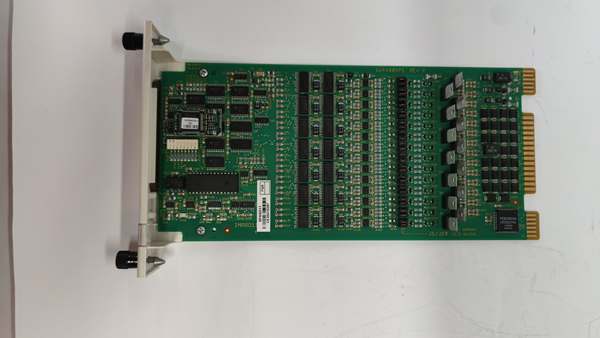
Key Technical Specifications
| Parameter | Value |
|---|---|
| Full Model Code | |
| Number of Analog Output Channels | 14 group-isolated output loops |
| Supported Output Signal Ranges | 4–20 mA current loop, 1–5 VDC voltage |
| D/A Conversion Resolution | 12-bit precision |
| Full-Scale Accuracy | ±0.1% FS at nominal operating temperature |
| Galvanic Isolation Rating | 1500 VAC group isolation between field output loops and rack backplane logic circuits |
| Max Load Resistance (4–20mA) | 500 Ω per channel maximum load |
| Built-In Protection Suite | Output constant current limiting, short-circuit auto shutdown with auto recovery, reverse polarity blocking |
| Backplane Communication | Symphony proprietary parallel backplane bus to master controller |
| Logic Power Supply | 24 VDC ±10% supplied via rack backplane, no separate external wiring required |
| Front Panel Indicators | Green POWER LED (normal power), Red FAIL LED (loop fault / communication loss) |
| PCB Surface Protection | ISA 71.04 G3 conformal coating for anti-moisture, anti-salt fog industrial environments |
| Mechanical Installation | Standard dedicated slot insertion inside Symphony Plus control rack |
| Operating Ambient Temperature | -10 °C ~ +60 °C sealed cabinet; storage temperature -40 °C ~ +85 °C |
| Humidity Tolerance | ≤75% RH non-condensing indoor control room rated |
| Overall Module Dimensions | 272 mm D × 130 mm W × 25 mm H |
| Net Weight | Approx. 0.75 kg |
| Compliance Standards | IEC 60282, IEC 62271-200 switchgear standard, IEC 60255 process control equipment, CE certified |
Product Introduction
The is the standard high-density analog output slave module for all ABB Symphony Plus DCS control room layouts, acting as the control signal output bridge between DCS master logic and field process actuators. It solves two core limitations of low-channel analog output boards: insufficient control channel capacity and poor anti-interference performance in multi-actuator industrial environments.
Three Core Functional Modules
- 14 High-Density Isolated Analog Output LoopsEach unit provides 14 independent analog control channels, greatly reducing the total number of I/O rack slots required for large-scale process plants. Every channel supports both 4–20mA valve control loops and 1–5VDC local meter feedback signals without factory jumper modification, unifying spare part inventory for multi-section production lines.
- Group Galvanic Isolation Anti-Interference DesignThe integrated isolation barrier blocks ground loop surge voltage and high-frequency EMI noise generated by MCC motor starters and large drive inverters, eliminating output signal distortion and random valve hunting caused by unbalanced field ground potentials. If one channel suffers short-circuit fault, the isolation circuit prevents fault spread to other 13 output loops to avoid full-section process control outage.
- Continuous Channel Self-Diagnosis & Fault AlarmThe front red FAIL LED monitors all 14 output loops in real time. When a field valve wire breaks, short-circuits or suffers polarity reversal, the fault indicator illuminates and records the exact faulty channel number in the DCS event log, allowing maintenance engineers to locate defective field wiring without scanning all output channels one by one.
The full conformal coating treatment extends service life in coastal distribution substations and chemical workshops with corrosive vapor. Typical application scenarios include boiler steam valve regulation, chemical reactor feed flow control, paper machine tension actuator positioning and cooling water pump speed adjustment. Without a functional , all 14 connected field actuators lose control signals and cannot execute automatic closed-loop process regulation.
QA & Testing SOP (Transparency Building)
- Incoming Visual Inspection: Cross-check full model against ABB Symphony Plus spare parts database to reject mismatched low-channel output modules; inspect front POWER/FAIL LED indicators, rear backplane gold-plated connector pins, field terminal block and conformal PCB coating for oxidation, discoloration or pin bending damage; record serial numbers and production batches for full maintenance traceability.
- Full Multi-Channel Linkage Bench Test: Mount into standard Symphony Plus rack test backplane, connect 14-channel simulated valve load banks; supply stabilized 24VDC rack logic power, run 24-hour cyclic testing including full-range 4–20mA / 1–5V output accuracy, individual channel short-circuit fault trigger auto-lockout and recovery, verify stable digital setpoint transmission from master controller to output loops without signal offset.
- Electrical Insulation Test: Use insulation resistance tester to confirm ≥ 10 MΩ isolation between each group of field output loops and rack backplane logic circuits; test chassis protective earth continuity resistance below 0.5 Ω.
- Hardware Record Backup: Photograph front LED fault status definitions and rear backplane slot mounting rules for field cabinet wiring reference.
- Final QC Packaging: Wipe module housing with anti-static microfiber cloth, cover all field terminal blocks and rear backplane connector with insulating dust caps, place the board into independent ESD shielding bag, attach unified printed QC test tag with full 24-hour multi-channel cyclic test runtime timestamp, then pack into foam shockproof carton for long-distance power plant transportation.
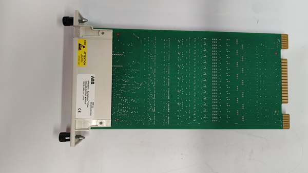
Installation Pitfalls & 4-Step Replacement Guide
Common Installation Hazards
❗ Residual DC Surge Risk: Before extracting the module, fully lock out the cabinet 24VDC auxiliary power supply feeding the DCS rack, wait for internal backplane capacitor complete discharge to avoid signal surge damaging controller CPU.❗ Output Load Over-Calculation Risk: Do not connect field actuators with total loop resistance exceeding 500Ω per channel; excessive load will activate persistent current limiting protection and cut off control signal output.❗ Channel Polarity Reversal Damage Risk: Every analog output terminal must follow positive/negative field actuator wiring sequence; reversed polarity will trigger channel protection lockout and disable control of that loop.❗ ESD PCB Damage Prevention: Mandatory anti-static wrist strap for all disassembly and installation work; bare finger contact with internal D/A conversion chips permanently impairs analog output precision and fault diagnosis logic.❗ Slot Alignment Installation Rule: Insert the module straight into the dedicated analog output rack slot; forced skewed insertion will scratch gold-plated backplane pins and create permanent intermittent channel contact loss.
4-Step Rack I/O Module Replacement Guide
- Pre-install Preparation: Lock out and tag out the 24VDC cabinet auxiliary power supply for the Symphony Plus DCS rack, wait for capacitor full discharge, wear ESD wrist strap, photograph rear backplane slot position and front field analog terminal wiring connected to 14-channel valve actuator terminals.
- Removal Operation: Unplug all field analog signal wires from front terminal blocks one by one following photographed records, release front module latch, slide the old board fully out of the rack backplane slot.
- Installation & Wiring: Align new module with the analog output rack slot rail, slide fully inward until front latch clicks locked; re-terminate all 4–20mA / 1–5V field actuator wires strictly following photographed wiring sequence, tighten terminal screws to ABB standard torque values.
- Power-on Commissioning Test: Restore cabinet 24VDC auxiliary control power, observe front green POWER LED steady on with red FAIL LED off; send setpoint commands from DCS master controller to each channel, verify accurate analog output signal to field actuators without fluctuation, simulate single-channel wire breakage to confirm red FAIL LED triggers and fault channel number logs correctly to plant SCADA system.
FAQ
Q: What is the difference between and low-channel analog output modules?Standard low-channel analog output boards only support half the control channel quantity of , requiring twice as many rack slots for identical field actuator layouts. features group galvanic isolation to suppress industrial EMI interference, while most small low-density output modules use non-isolated shared circuit design, prone to cross-channel signal crosstalk. The two cannot be cross-replaced without recalculating total cabinet I/O control channel capacity.
Q: Can operate without connecting to a Symphony Plus master controller?No. is a passive slave output board without independent control logic or D/A conversion processing capability. It relies entirely on the rack backplane Symphony bus to receive digital setpoint commands from the master CPU; without a matched master controller, all 14 output channels cannot generate analog control signals.
Q: Can be hot-swapped with rack 24VDC auxiliary power energized?Strictly prohibited. The module mates directly with the live Symphony rack backplane low-voltage logic bus; live extraction will generate signal surge voltage and permanently damage CPU backplane communication circuits. Full auxiliary DC power lockout is mandatory before replacement.
Q: What warranty applies to stocked modules?Factory-new original legacy DCS analog output modules carry a 12-month official ABB manufacturer warranty covering all 14-channel D/A conversion circuits, group isolation transformers, output current limiting protection and front diagnostic indicators. Bench-tested surplus modules provide a 6-month functional warranty; damage caused by field polarity reversal, live hot-swap disassembly or ungrounded ESD handling voids all warranty terms.
Q: Has ABB discontinued production?Yes, the entire ABB Symphony Plus Bailey Infi 90 DCS platform including output module is fully end-of-life. New industrial and power plant DCS projects adopt ABB 800xA systems with S800 remote I/O modules without separate SPAS series rack-slotted analog output boards. is only available as limited stock maintenance spare parts for legacy Symphony control room renovation.
Q: What typical faults indicate a defective module?Common failure symptoms: Permanent red FAIL LED alarm with intact field actuator wiring, random single-channel analog control loss without field cable damage, severe output signal distortion under normal load operation, failure to send fault alarm signals to DCS after field loop short-circuit, front POWER LED fails to illuminate after rack auxiliary power restoration, inability to adjust actuator position via DCS setpoint commands.




