
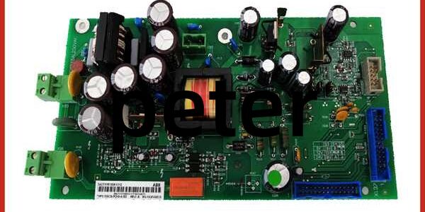
Product Core Brief
- Model: SDCS-POW-4 (No single standalone 1MRK part number; standard drawing code: 3ADW000194R0201)
- Brand: ABB Hitachi Energy
- Series: ABB DCS800 large frame D5/D6/D7 thyristor DC drive dedicated internal auxiliary power supply board
- Core Function: Flyback topology switched-mode power supply mounted on the top electronic tray inside DCS800 D5/D6/D7 power drawers. It automatically detects 115 VAC or 230 VAC single-phase auxiliary mains input and converts it into multiple stabilized isolated DC output rails to power all internal drive electronics: SDCS-CON-4 main CPU, SDCS-PIN-51 measuring board, SDCS-PIN-48-SD pulse trigger board, SDCS-COM-81 fieldbus communication subboard and incremental speed encoderseero.Exclusive built-in functions:
- Jumper-selectable encoder supply (5 V / 12 V / 15 V) for DC motor speed feedback;
- Integrated normally-open relay contact controlled by drive digital output 8 for main circuit breaker interlock/alarm signal output to DCS;
- Parallel drive synchronization interface via X14 connector for multi-unit hard parallel DC drive systems;
- Complete hardware protection suite to prevent downstream control board burnout from mains surge, overload and short-circuit faultseero.
- Product Type: DCS800 drawer internal multi-output flyback switch-mode power supply PCB
- Key Specs: Auto-sensing AC input 85–264 VAC (115/230 V nominal); multiple isolated low-noise DC output rails for CPU, logic, fieldbus and encoder; encoder voltage selectable 5/12/15 V via on-board jumpers; built-in mains EMC filter; integrated relay contact for breaker control; input reverse polarity, overvoltage, output constant current limiting, short-circuit auto-recovery shutdown; full galvanic isolation between AC primary and DC secondary circuits; flat cable backplane connection X37/X137 to SDCS-CON-4; top tray fixed mounting inside D5/D6/D7 power drawers only
- Note: The DCS800 platform is fully end-of-life; only remaining factory-sealed original boards and fully load-tested surplus PCBs are supplied as maintenance spares for steel rolling mills, thermal power generator excitation bays, paper calender multi-section DC drives and heavy industrial MV motor control cabinets. Not compatible with small D1-D4 frames (those use smaller SDCS-POW-2 power boards).
Key Technical Specifications
| Parameter | Value |
|---|---|
| Official Drawing Code | 3ADW000194R0201 () |
| AC Mains Input | Auto-range 85 ~ 264 VAC, 47–63 Hz single-phase, auto 115/230V detection |
| Topology | Flyback isolated switch-mode power supply |
| Multi DC Output Rails | Stabilized low-noise isolated voltages for CPU logic, fieldbus transceivers, pulse trigger circuits and encoder feedback |
| Encoder Output Selection | Jumper S3/S4/S5 selectable: 5 V, 12 V, 15 V |
| Built-In Relay Contact | 1 x NO Form-A contact rated 250 VAC / 24 VDC for main breaker trip/alarm |
| Protection Suite | Input overvoltage lockout, reverse polarity blocking, output constant current limiting, auto-recovery short-circuit shutdown, overtemperature thermal cut-off |
| Isolation Rating | 2000 VAC functional isolation between AC mains primary and low-voltage control DC secondary |
| Main Interfaces | X99: AC mains input; X37/X137: Parallel flat cable to SDCS-CON-4; X96: Breaker relay contact output; X14: Multi-drive parallel synchronization |
| Mechanical Mounting | Fixed top position on D5/D6/D7 electronic tray, cannot be installed in D1-D4 small drawers |
| Operating Ambient Temp | -10 °C ~ +55 °C sealed control cabinet; storage: -40 °C ~ +70 °C |
| Humidity Class | ≤75% RH non-condensing indoor control room rated |
| Net Weight | Approx. 2.0 kg |
| Compliance Standards | IEC 60255 process control equipment, IEC 61010 power supply safety, CE & RoHS certified |
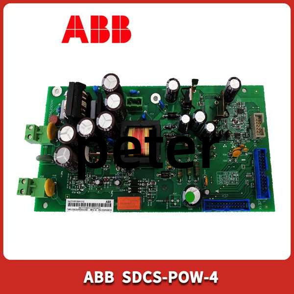
Product Introduction
The is the sole central auxiliary power backbone for all large-frame D5/D6/D7 DC converter drawers, solving the core limitation of small low-power POW-2 boards that cannot supply heavy multi-board control loads.
Four Core Design Advantages
- Universal Auto-Sensing AC Input CompatibilityNo manual voltage selector switch required; the board automatically adapts to 115 VAC or 230 VAC industrial cabinet control power, unifying spare part inventory for multi-region power plants and factories. Integrated multi-stage EMC filter suppresses high-frequency mains surge noise generated by MCC and thyristor switching to eliminate CPU signal drift and random drive tripseero.
- Adjustable Multi-Voltage Encoder Power SupplyOn-board jumpers allow maintenance engineers to switch encoder output between 5 V, 12 V and 15 V without replacing power boards, matching all standard DC motor incremental speed feedback encoders used in rolling mills and paper machines. Encoder power can be sourced either from or the SDCS-CON-4 main board via jumper configurationManualsLib.
- Instead of installing an extra external auxiliary relay cabinet, embeds a dedicated relay contact controlled by drive digital output DO8. When critical drive faults (severe short-circuit, overheat, sustained reverse power) occur, the contact closes to trip the upstream AC input breaker and sends fault alarm signals to plant SCADA/DCS systems, simplifying secondary circuit layout and reducing cabinet component counteero.
- Multi-Drive Parallel Synchronization SupportThe X14 dedicated connector enables multiple drawers to share synchronized power reference signals for parallel heavy-load DC drive systems (steel roughing mills, large generator excitation cabinets). The flyback circuit delivers ultra-low ripple DC power to prevent analog measurement distortion and unstable closed-loop speed regulation.
All internal circuits carry anti-corrosion conformal coating as standard to resist moisture and mild industrial corrosive vapor. Without a functional , every control board inside the D5/D6/D7 drawer loses all operating power, resulting in full drive shutdown and production interruption. It cannot operate standalone and must connect to the SDCS-CON-4 main control board via the supplied flat backplane cable.
QA & Testing SOP (Transparency Building)
- Incoming Visual Inspection: Cross-check model and drawing code 3ADW000194R0201 against ABB spare parts database to reject D1-D4 POW-2 mismatched boards; inspect front status LED, AC input/output terminal blocks, internal flyback transformer, encoder jumper bank and conformal coating for burn marks, discoloration or mechanical cracking; record serial numbers and production batches for full traceability.
- Full Load Bench Linkage Test: Mount on standard D5/D7 electronic tray test bench, supply variable 85–264 VAC mains input; connect full simulated load bank represen, PIN-51, PIN-48-SD and COM-81 boards; run 24-hour cyclic full-load testing, simulate mains dropout to verify stable hold-up output, test encoder 5/12/15V voltage switching, trigger overcurrent/overtemperature short-circuit faults to confirm protection lockout and auto-recovery, verify breaker relay contact reliable closure under fault conditions.
- Electrical Insulation Test: Use insulation resistance tester to confirm isolation resistance ≥ 10 MΩ between high-voltage AC primary circuits and all low-voltage DC output rails; test chassis protective earth continuity resistance below 0.5 Ω.
- Hardware Record Backup: Photograph encoder voltage jumper definitions, X99/X96/X14 terminal pin assignments and flat cable backplane wiring sequence for field commissioning reference.
- Final QC Packaging: Wipe module housing with anti-static microfiber cloth, cover all AC/DC terminal blocks and front jumper slots with insulating dust caps, place the unit into independent ESD shielding bag, attach unified printed QC test tag with full 24-hour full-load test runtime timestamp, then pack into foam shockproof carton for long-distance power plant transportation.
Installation Pitfalls & 4-Step Replacement Guide
Common Installation Hazards
❗ Lethal Residual High-Voltage Capacitor Risk: After cutting off cabinet AC mains power feeding , wait minimum 10 minutes for internal primary and secondary DC bus capacitors to fully discharge before disassembly to avoid severe electric shock.❗ Frame Size Mismatch Prohibition: only fits D5/D6/D7 large drawers; forced installation into D1-D4 small frames will damage tray backplane connectors and trigger permanent power supply overload.❗ Encoder Jumper Misconfiguration Risk: Incorrect S3/S4/S5 jumper setting will apply wrong voltage to motor encoders, instantly burning encoder internal circuits and losing speed feedback signals.❗ Mandatory PE Earth Connection: is Class I safety equipment; missing protective earth wire invalidates insulation safety certification and creates electric shock hazards during internal circuit breakdown.❗ ESD PCB Damage Risk: Wear certified anti-static wrist strap during all disassembly and installation work; bare hand contact with internal flyback switching chips permanently impairs multi-rail output stability and encoder voltage regulation accuracy.
4-Step Tray Power Board Replacement Guide
- Pre-install Preparation: Lock out and tag out the cabinet AC mains auxiliary power supply feeding the drawer, wait 10+ minutes for complete capacitor discharge, wear ESD wrist strap, photograph X99 AC input wiring, X96 breaker relay signal wiring, X14 parallel synchronization wiring and X37 flat cable connectio main control board.
- Removal Operation: Unplug X37 flat cable connectin first; loosen all X99, X96 and X14 terminal wire screws, release the top tray mounting fasteners, detach the old board from the electronic tray.
- Installation & Wiring: Fix the new module onto the original top tray mounting position; replicate AC mains input polarity, breaker relay output and parallel drive wiring strictly following photographed sequences; adjust encoder voltage jumpers S3/S4/S5 to match on-site motor encoder rating; re-plug X37 flat cable fully into backplane connector.
- Power-on Commissioning Test: Restore cabinet AC mains power, observe front green RUN LED steady on with no fault flashing; measure encoder output terminal voltage to confirm jumper setting matches specification; CPU and all connected measuring/communication boards, verify all drive functions initialize normally without power fault alarms on DCS/SCADA system; simulate fault trigger to confirm breaker relay contact closes reliably.
FAQ
Q: What is the difference between SDCS-POW-2 and ?
- SDCS-POW-2: Low-power variant for small D1-D4 drawers, limited output capacity, no built-in breaker relay contact, no multi-voltage encoder jumper selection;
- : High-power heavy-load version for D5/D6/D7 large frames, higher total output power, integrated breaker trip relay, 5/12/15V encoder selectable supply and multi-drive parallel synchronization interface. The two cannot be cross-replaced due to different tray mechanical dimensions and power load capacity.
Q: Can operate without connecting main control board?No. The X37 flat cable carries both power and bidirectional diagnostic signal lines between POW-4 and . Without the connection, the power supply’s fault protection logic and relay contact control functions are disabled, and the encoder power rail may lose stable regulation.
Q: Can be hot-swapped with cabinet AC mains energized?Strictly prohibited. The board connects directly to live high-voltage AC mains input terminals and charged internal DC bus capacitors; live disassembly will generate severe DC arc flash and permanently damage flyback switching semiconductors. Full AC mains lockout and capacitor discharge waiting time are mandatory before replacement.
Q: What warranty applies to stocked boards?Factory-new original DCS power supply PCBs carry a 12-month ABB official warranty covering flyback conversion circuits, multi-rail output regulation, encoder voltage control and built-in relay contact hardware. Bench-tested surplus modules provide a 6-month functional warranty; damage caused by residual high-voltage shock, encoder jumper misconfiguration, mains polarity reversal or ungrounded ESD handling voids all warranty coverage.
Q: Has ABB discontinued production?No formal EOL notice issued; remains standard supply for legacy D5/D6/D7 drawer cabinet renovation projects. New industrial DC drive systems adopt DCS880 series with fully integrated on-board power supplies that eliminate separate SDCS-POW auxiliary boards.
Q: What typical faults indicate a defective power board?Common failure symptoms: Front RUN LED flashes continuously (protection lockout) after mains power restoration, downst CPU fails to boot up, unstable fluctuating encoder supply voltage leading to random speed feedback loss, failure of breaker relay contact to close during drive faults, severe overheating of the power board housing under normal rated load, permanent loss of one or more DC output rails with normal AC mains input.




