
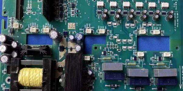
Product Core Brief
- Model: SINT4611C
- Brand: ABB Hitachi Energy
- Series: ABB ACS510 / ACS550 general-purpose industrial variable frequency drive power stage core board
- Core Function: Integrated composite power PCB exclusively for high-power ACS510/ACS550 inverters (132kW ~ 160kW frame sizes). It combines two core functions in one single board:
- Wide-range AC-DC switch-mode auxiliary power supply, converting three-phase mains rectified DC into multi-channel isolated stabilized low-noise logic power for the drive CPU, current sampling circuits and gate driver chips;
- Independent three-channel isolated IGBT gate pulse trigger driver, outputting amplified optical isolated gate signals to control the upper/lower arm IGBT power modules for motor speed & torque regulation.It integrates built-in shunt current sampling resistors to collect real-time output current signals for overload, short-circuit and overcurrent protection. Full hardware protection suite (input reverse polarity, output overcurrent, IGBT short-circuit auto-lockout, overheat thermal shutdown) prevents power module burnout during abnormal operation. is the high-power version, upgraded from small-capacity SINT4610C for 132/160kW heavy-load drive applications.
- Product Type: VFD integrated power supply + IGBT gate trigger driver PCB
- Key Specs: Matched with ACS510/ACS550 132kW, 160kW high-power inverters; built-in flyback SMPS multi-rail isolated DC output; 3 independent galvanically isolated IGBT gate drive channels; on-board shunt resistors for real-time output current sampling; integrated NTC temperature monitoring for power heat sink; full OVP/OCP/SCP thermal protection; epoxy insulated high-current copper traces; conformal anti-corrosion coated PCB; compatible with ABB main control boards SMIO-01C / SMIO-02C
- Note: Still active OEM production for new fan/pump/compressor VFD projects and legacy industrial drive cabinet maintenance; factory-sealed original boards and fully load-tested surplus PCBs are widely supplied for water treatment plants, HVAC air conditioning systems, chemical plant conveying equipment and mining fan control cabinets. Cannot be interchanged with low-power SINT4610C for 132kW+ frames due to insufficient current carrying capacity.
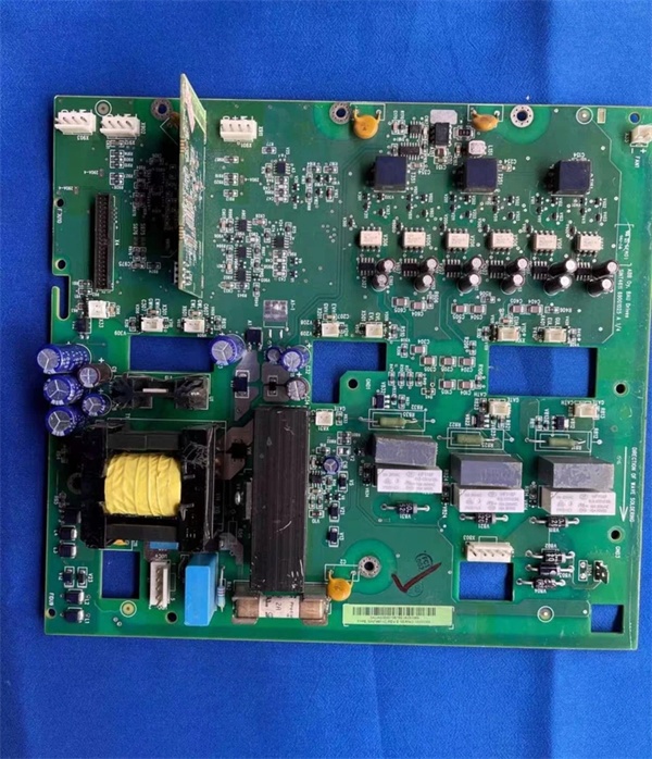
Key Technical Specifications
| Parameter | Value |
|---|---|
| Full Model Number | |
| Compatible Drive Frames | ACS510 / ACS550 132kW, 160kW high-power models |
| Mains DC Input | Rectified three-phase DC bus voltage from drive rectifier bridge |
| Internal SMPS Output Rails | Multiple isolated low-noise DC voltages for CPU logic, gate driver IC, sampling circuits |
| IGBT Drive Channels | 3 independent galvanic isolated gate drive channels for U/V/W three-phase inverter arms |
| Current Sampling Hardware | On-board precision shunt resistors for real-time motor output current detection |
| Temperature Monitoring | Built-in NTC thermistor interface for power heat sink overheat protection |
| Protection Circuit Suite | Input reverse polarity blocking, DC bus overvoltage lockout, output constant current limiting, IGBT short-circuit auto shutdown, thermal overtrip |
| PCB Surface Treatment | ISA G3 conformal coating for high-humidity industrial environments |
| Mechanical Installation | Fixed bracket mounting inside ACS510/ACS550 power drawer, mates with main control board via flat cable backplane |
| Operating Ambient Temp | -10 °C ~ +55 °C sealed drive cabinet; storage temperature -40 °C ~ +70 °C |
| Humidity Tolerance | ≤75% RH non-condensing, indoor industrial cabinet rated |
| Net Weight | Approx. 1.1 kg |
| Compliance Standards | IEC 61800 variable frequency drive standard, UL 508, CE & RoHS certified |
Product Introduction
The is the heart of high-power ABB / VFDs, integrating auxiliary power generation and IGBT gate driving functions that were split into two separate boards on small low-power drives. It solves two critical industrial drive pain points: separate power supply & trigger board layout and insufficient current capacity for heavy-load 132/160kW motor applications.
Four Core Functional Modules
- Integrated Flyback SMPS Auxiliary Power SourceThe built-in switching power circuit takes high-voltage rectified DC from the drive’s three-phase input and converts it into multiple stabilized low-voltage isolated DC rails. It powers all low-voltage control hardware including the main CPU board, current sampling chips and optical gate drivers, eliminating the need for an independent external auxiliary power module and saving cabinet internal space.
- Three-Channel Isolated IGBT Gate Pulse TriggerOptically isolated gate drive amplifiers receive PWM pulse commands from the SMIO main control board, then output high-current drive signals to switch the three-phase IGBT power modules. Galvanic isolation completely blocks DC bus surge noise and ground loop interference to avoid false IGBT switching and motor speed fluctuation.
- Real-Time Output Current Sampling & Protection LogicPrecision shunt resistors on the PCB continuously measure motor output current. The sampled analog signals are fed back to the CPU to execute overload, stall and short-circuit protection curves. Once abnormal current exceeds the threshold, the board immediately cuts off all gate drive pulses to isolate the faulty motor branch and protect expensive IGBT power modules from permanent burnout.
- Heat Sink Overheat MonitoringDedicated NTC thermistor interface monitors power module heat sink temperature. If heat sink temperature rises above the safety threshold, the board triggers staged alarm and slow-down/trip logic to prevent thermal breakdown of IGBT chips under continuous heavy-load operation.
The conformal coating treatment prevents PCB oxidation and signal distortion in high-humidity, dusty water treatment and chemical plant environments. Without a functional , the entire / drive cannot generate motor output voltage and will remain in permanent fault lockout state.
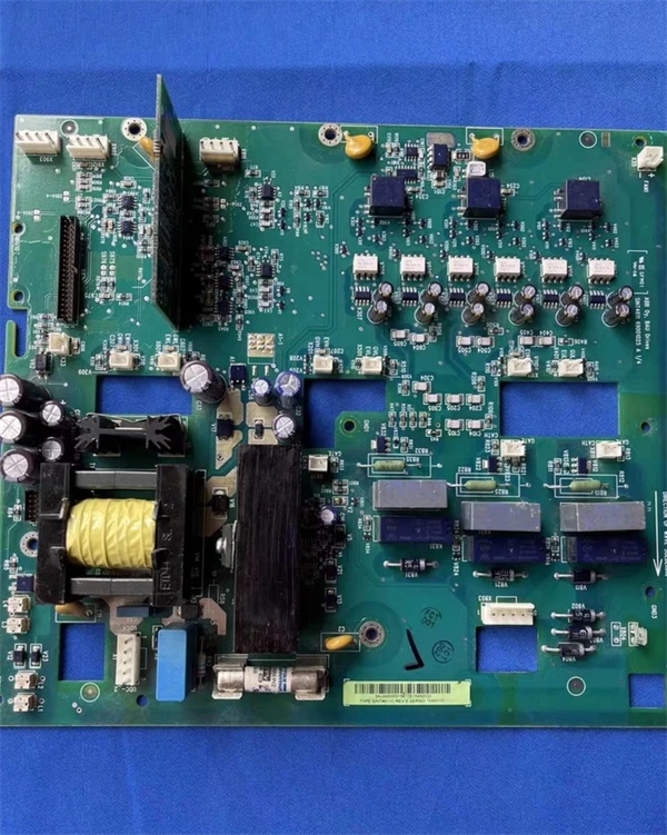
QA & Testing SOP (Transparency Building)
- Incoming Visual Inspection: Cross-check full model and serial number against ABB VFD spare parts database to reject low-power SINT4610C mismatched boards; inspect front terminal blocks, internal flyback transformer, three-channel gate drive circuits, shunt sampling resistors and conformal coating for swelling, electrolyte leakage, blackened overheating marks or pin bending damage; record serial numbers and production batches for full traceability.
- Full Linkage Bench Test: Mount into standard 160kW test drawer, connect matched SMIO main control board and simulated motor load bank; supply variable rectified DC bus input, run 24-hour cyclic testing including full-load PWM three-phase output, power failure hold-up simulation, overload/short-circuit fault trigger auto-lockout, NTC overheat protection activation, verify stable isolated SMPS output voltage without ripple distortion under all load conditions.
- Electrical Safety Test: Use insulation resistance tester to confirm isolation resistance ≥ 10 MΩ between high-voltage DC bus circuits and low-voltage control signal circuits; test chassis ground continuity resistance below 0.5 Ω.
- Hardware Record Backup: Photograph flat cable backplane connector pin definitions and cabinet mounting bracket dimensions for field maintenance reference.
- Final QC Packaging: Wipe module housing with anti-static microfiber cloth, cover all high-voltage terminal blocks with insulating dust caps, place the board into independent ESD shielding bag, attach unified printed QC test tag with full 24-hour full-load test runtime timestamp, then pack into foam shockproof carton for long-distance industrial plant transportation.
Installation Pitfalls & 4-Step Replacement Guide
Common Installation Hazards
❗ Lethal DC Bus Residual High-Voltage Risk: After cutting off three-phase AC mains power feeding the VFD, wait minimum 15 minutes for DC bus filter capacitors to fully discharge before opening the power drawer and removing to avoid fatal electric shock.❗ Model Mismatch Cross-Replacement Risk: is exclusive for 132/160kW high-power frames; installing SINT4610C low-power board will trigger persistent overload protection and frequent drive tripping under rated motor load.❗ IGBT Gate Terminal Wiring Polarity Error: Misconnected gate positive/negative terminals will lead to uncontrolled IGBT conduction and severe DC bus short-circuit faults that destroy power modules instantly.❗ ESD PCB Damage Risk: Wear certified anti-static wrist strap during all disassembly and installation work; bare hand contact with internal gate drive ICs and flyback switching semiconductors permanently impairs PWM pulse output accuracy and protection logic function.❗ Overheat Heat Sink Contact Risk: Ensure the NTC thermistor makes tight contact with the IGBT heat sink; loose thermal contact disables overheat protection and creates hidden equipment damage risks.
4-Step Drive Power Board Replacement Guide
- Pre-install Preparation: Lock out and tag out the VFD cabinet three-phase AC mains power supply, wait 15+ minutes for DC bus capacitor complete discharge, wear ESD wrist strap, photograph flat cable backplane wiring connecting to SMIO main control board, three-phase IGBT gate wiring and DC bus input terminal positions inside the power drawer.
- Removal Operation: Unplug all flat communication cables and IGBT gate signal wires one by one following photographed records, loosen mounting bracket fixing bolts, detach the old board from the internal power drawer frame.
- Installation & Wiring: Fix the new module onto the original mounting bracket with standard torque bolts; re-terminate DC bus input, three-phase IGBT gate drive and SMIO control flat cable wiring strictly following photographed sequence, ensure NTC thermistor tightly attaches to the power heat sink surface.
- Power-on Commissioning Test: Restore cabinet three-phase AC mains power, observe front drive RUN status indicator steady on without fault alarm; run motor no-load test for 1 hour, verify smooth three-phase speed regulation without current distortion, simulate overload and short-circuit fault signals to confirm reliable protection lockout, check DCS/SCADA system receives normal drive running data without power fault alarms.
FAQ
Q: What is the core difference between SINT4610C and ?
- : Low-power variant for / below 110kW frames, smaller current carrying capacity, thinner copper traces, lower power SMPS output;
- : High-power heavy-load version for 132kW / 160kW large drives, thicker high-current conductive copper traces, upgraded gate drive amplifier circuits, higher total SMPS output power to support multi-channel heavy-load control hardware. The two cannot be cross-replaced without recalculating drive total load current.
Q: Can operate without connecting the SMIO main control board?No. The only provides power and gate drive hardware; all PWM pulse generation, current threshold setting and fault diagnosis logic are stored on the SMIO CPU board. Without the main control board, the gate drive channels will not output switching pulses and the drive cannot start the motor.
Q: Can be hot-swapped with cabinet AC mains energized?Strictly prohibited. The board connects directly to live high-voltage DC bus capacitors and charged gate drive signal loops; disassembly under energized conditions will generate severe DC arc flash and permanently damage internal switching power and gate drive semiconductors. Full three-phase mains lockout and 15-minute capacitor discharge waiting time are mandatory before replacement.
Q: What warranty applies to stocked modules?Factory-new original ABB VFD power boards carry a 12-month official manufacturer warranty covering flyback SMPS conversion circuits, three-channel IGBT gate drive hardware, current sampling shunt resistors and thermal protection logic. Bench-tested surplus units provide a 6-month functional warranty; damage caused by DC bus residual voltage shock, gate wiring polarity reversal, sustained overload operation or ungrounded ESD handling voids all warranty coverage.
Q: Has ABB discontinued production?No formal EOL notice has been released; remains standard supply for legacy / high-power drive cabinet renovation projects. New ABB industrial VFD series (ACS580, ACS880) adopt redesigned modular power stack architecture with split separate power supply and trigger boards, no longer using integrated SINT series composite boards.
Q: What typical faults indicate a defective board?Common failure symptoms: Drive permanent fault alarm immediately after mains power restoration with normal AC input, random motor stall and tripping under rated load operation, severe distorted three-phase output current waveform without motor winding damage, failure to cut off gate pulses during short-circuit faults, NTC thermistor circuit failure leading to missing overheat protection, yellow READY status LED never lights up after power-on, unstable fluctuating internal logic supply voltage causing random CPU communication loss.




