
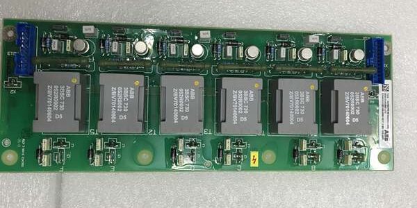
Product Core Brief
- Model: SDCS-PIN-48-SD, official OEM drawing code: 3ADT315200R1002
- Brand: ABB Hitachi Energy
- Series: ABB DCS800 series thyristor-based DC variable speed converter main power trigger PCB
- Core Function: Passive pulse transformer isolation board that receives low-power gate trigger pulse signals from the SDCS-CON-4 main control board, then generates isolated high-energy firing pulses to drive the thyristor rectifier bridge in DCS800 power drawers. The SD suffix variant integrates optimized transformer winding ratios and RC absorption circuits to eliminate cross-phase pulse crosstalk and suppress 2nd harmonic magnetizing inrush currents for transformer and heavy motor feeder bays. It provides full galvanic isolation between low-voltage control logic circuits and high-power thyristor primary circuits to block surge voltage backfeed and protect the SDCS-CON-4 CPU from power stage breakdown.
- Product Type: Power drawer internal pulse trigger transformer printed circuit board
- Key Specs: Multi-channel independent pulse transformer windings for each thyristor branch; built-in RC snubber harmonic suppression network; functional isolation between control side and thyristor high-power side; ultra-low logic circuit burden; compatible with all DCS800 frame sizes D1 to D7; no separate auxiliary power required, powered via DDCS fiber signal loop from SDCS-CON-4; conformal anti-corrosion PCB coating; cabinet power drawer fixed bracket installation
- Note: The entire DCS800 DC drive platform including SDCS-PIN-48-SD is fully end-of-production. Only limited factory-sealed original trigger boards and fully bench-load-tested surplus PCBs are supplied as maintenance spares for metallurgical rolling mills, thermal power generator excitation DC drives, paper calender multi-section DC drive systems and coastal industrial MV switchgear retrofits. Mandatory matching component with SDCS-CON-4-COAT-ROHS main control board.
Key Technical Specifications
| Parameter | Value |
|---|---|
| Full OEM Article Code | SDCS-PIN-48-SD (3ADT315200R1002) |
| Trigger Circuit Structure | Multi-channel independent pulse transformer per thyristor branch with isolated primary/secondary windings |
| Harmonic Suppression (SD suffix) | Integrated RC snubber filter to attenuate 2nd harmonic transformer inrush interference |
| Galvanic Isolation Rating | ≥ 3000 VAC isolation between low-voltage control pulse side and high-power thyristor gate side |
| Pulse Transmission Characteristic | Linear pulse transmission with minimal delay, no signal distortion under full short-circuit current transients |
| Control Circuit Burden | Ultra-low burden on SDCS-CON-4 logic output channels to avoid pulse attenuation |
| Thyristor Compatibility | Matched with all rated thyristor power modules (1A/5A CT secondary standard) |
| Mechanical Installation | Fixed bracket mounting inside power drawer between control board and thyristor stack |
| Continuous Operating Ambient Temp | -20 °C ~ +50 °C sealed cabinet operation; storage temperature -40 °C ~ +70 °C |
| Humidity Class | ≤95% RH non-condensing, indoor control room rated |
| PCB Surface Treatment | ISA 71.04 G3 conformal coating for salt fog and corrosive gas resistance |
| Overall Dimensions | 260 mm L × 160 mm W × 22 mm D |
| Net Weight | Approx. 450 g |
| Compliance Standards | IEC 61800-3 EMC for variable speed drives, IEC 60255 power equipment standard, CE & RoHS certified |
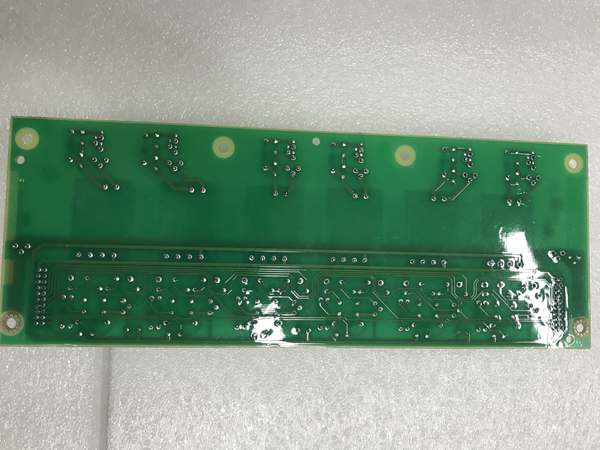
Product Introduction
he is a critical passive trigger hardware componeide power drawers, serving as the electrical isolation bridge between the low-voltage control motSDCS-CON-4) and high-power thyristor rectifier stacks. Its SD suffix customized harmonic filter design eliminates the most common failure cause of standard trigger boards: false thyristor firing during transformer energization caused by magnetizing inrush harmonics.
Three Core Functional Mechanisms
- Galvanic Isolation Safety BarrierThyristor stacks connect directly to three-phase industrial high-voltage mains, which carry severe surge voltage and EMI noise. The multi-winding pulse transformer creates a complete isolation barrier to prevent high-voltage surge backflow into the CPU board, eliminating permanent microprocessor breakdown risks during grid short-circuit faults.
- Controlled Thyristor Gate Pulse Generation & Inrush FilteringThe SD exclusive RC harmonic filter suppresses 2nd harmonic currents generated by transformer magnetizing inrush. Without this filter, standard trigger boards will produce random false gate pulses when upstream transformers switch online, triggering unplanned drive tripping and production interruption. It transmits accurate phase-angle firing pulses to each thyristor branch to maintain precise DC voltage regulation and protection coordination.
- Multi-Channel Independent Pulse DistributionSeparate transformer windings for each thyristor phase eliminate cross-channel signal crosstalk, ensuring balanced three-phase rectifier operation under unbalanced grid voltage conditions. The ultra-low control circuit burden avoids pulse amplitude attenuation even when multiple drive units run in parallel on the same bus.
The conformal coating treatment enables long-term stable operation in offshore wind turbine control cabinets and metallurgical workshops with corrosive fumes. It cannot work independently; every power drawer requires oal to realize thyristor rectification and DC motor speed regulation.
QA & Testing SOP (Transparency Building)
- Incoming Visual Inspection: Cross-cheel and OEM drawing number 3ADT315200R1002 against ABB power drive spare parts database to reject counterfeit mismatched trigger boards; inspect internal pulse transformer windings, RC snubber components, terminal screw blocks and conformal coating for winding cracking, blackened overheating marks or salt fog corrosion; record serial numbers and production batches for full traceability.
- Full Pulse Linkage Bencnt on standard power drawer test bench, connect matched control board to output variable firing pulse signals; run 24-hour cyclic testing to verify accurate pulse transmission to thyristor gate terminals, simulate transformer 2nd harmonic inrush mixed signals to confirm filter anti-false-firing performance, test cross-channel isolation without signal crosstalk.
- Electrical Insulation Test: Use insulation resistance tester to confirm isolation resistance ≥ 10 MΩ between low-voltage pulse input circuits and thyristor high-power output circuits; test chassis ground continuity resistance below 0.5 Ω.
- Hardware Record Backup: Photograph mounting bracket bolt positions and pulse signal terminal wiring sequence for field maintenance reference.
- Final QC Packaging: Wipe PCB housing with anti-static microfiber cloth, cover all terminal screw blocks with insulating protective caps, place the board into independent ESD shielding bag, attach unified printed QC test tag with technician ID and full 24-hour pulse cycle test runtime timestamp, then pack into foam shockproof carton for long-distance power plant transportation.
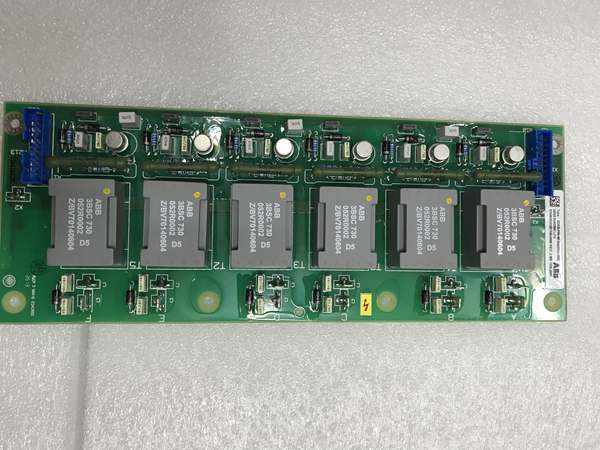
Installation Pitfalls & 4-Step Replacement Guide
Common Installation Hazards
❗ Lethal DC Bus Residual High Voltage Risk: After cutting off three-phase AC main power, wait minimum 15 minutes for full discharge of DC bus capacitors before opening the power drawerng to avoid electric shock.❗ Variant Mismatch Risk: SD suffix integrates harmonic suppression filter; direct replacement with non-filter variants for transformer feeder bays will cause frequent false thyristor firing and unplanned drive trips.❗ ESD PCB Damage Risk: Wear certified anti-static wrist strap during all disassembly and installation work; bare hand contact with internal pulse transformer windings will degrade isolation performance and cause pulse attenuation.❗ Loose Terminal Torque Defect: Under-tightened pulse signal terminals create high contact resistance, leading to incomplete thyristor firing and unbalanced DC output voltage during full-load operation; follow ABB specified torque values strictly.❗ Misaligned Phase Pulse Wiring: Swapped thyristor channel pulse terminals break rectifier phase balance and generate severe DC voltage ripple, damaging downstream DC bus capacitors and motor armature windings.
4-Step Trigger Board Replacement Guide
- Pre-install Preparation: Lock out and tag out the cabinet three-phase AC main input power feeding the power drawer, wait 15+ minutes for DC bus capacitor complete discharge, wear ESD wrist strap, photograph pulse signal wiring connected to control board and thyristor gate terminals, as well as fixed mounting boltof inside the drawer.
- Removal Operation: Loosen all pulse signal wire terhe PCB, unscrew the bracket fixing bolts, detach the old trigger board from the power drawer internal layout.
- Installation & Wiringew board onto the original mounting bracket with standard torque bolts; re-terminate all control pulse and thyristor gate wires strictly following photographed wiring sequence, ensure every terminal screw is fully tightened without loose strands.
- Power-on Commissioning Test: Restore main AC input power, run no-load DC drive operation for 1 hour, measure DC output voltage to confirm stable balanced rectifier operation; simulate transformer magnetizing inrush harmonic signals to verify no false thyristor firing, check DCS fault history for pulse trigger alarm codes and confirm continuous stable motor speed regulation.
FAQ
Q: What is the diffeen and standard ?
- : Transformer feeder dedicated variant, built-in RC 2nd harmonic filter to suppress magnetizing inrush and eliminate false thyristor firing; mandatory for transformer step-down bays.
- Standard : General-purpose trigger board without harmonic filter, only suitable for pure DC motor bays without transformer switching inrush interference. The two cannot be cross-replaced in transformer feeder layouts.
Q: What is the diffeen and RVAR-5612 surge board? is a pulse trigger transformer board locat control board and thyristor stack, responsible for gate pulse isolation and transmission. RVAR-5612 is an AC input surge protection PCB installed on the grid side of the power unit, absorbing lightning and switching voltage spikes. The two boards execute independent power stage functions and cannot replace each other.
an be hot-swapped wi energized?Strictly prohibited. The board connects to live thyristor gate secondary circuits and charged DC busbars; disassembly under energized conditions will trigger severe arc flash accidents and permanent breakdown of internal pulse transformer windings. Full main power lockout and capacitor discharge are mandatory before replacement.
Q: What warranty applied 3ADT315200R1002 boards?Factory-new original trigger PCBs carry 12-month official ABB manufacturer warranty covering pulse transformer winding isolation, RC harmonic filter circuits and terminal contact continuity. Bench-tested surplus boards provide 6-month functional warranty; damage caused by DC bus residual voltage shock, loose terminal overheating or ungrounded ESD handling voids all warranty terms.
Q: Has ABBed production?Yes, the entire DC drive platfng trigger board is fully end-of-production. New industrial DC drive projects adopt DCS880 series converters with integrated gate trigger hardware built into the thyristor power e; is only supplied as maintenance spare parts for legacy power plant and metallurgical rolling mill cabinet renovation.
Q: What typical faults indicatve trigger board?Common failure symptoms: Random false thyristor firing and DC voltage surge trips during transformer energization (filter circuit failure), unbalanced three-phase DC output voltage under normal load, failure to generate gate pulses leading to motor loss of torque, severe DC voltage ripple without grid abnormality, pulse signal attenuation causing unstable motor speed fluctuation, blackened transformer windings due to internal overheating.




