
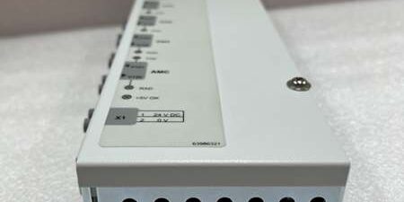
Product Core Brief
- Model:
- Brand: ABB Drives Division
- Series: ACS800 Multidrive cabinet PPCS fiber optical communication subsystem
- Core Function: 4-channel PPCS fiber branching unit; distributes master PPCS fiber bus signal to up to four independent inverter power modules inside an ACS800 multidrive cabinet, segregating optical communication paths between the main control unit and each slave inverter module without signal attenuationManualsLib
- Product Type: Slot-mounted internal optical branching PCB, exclusively for ACS800-104 multidrive power cabinets
- Key Specs: 4 independent PPCS optical receive/transmit channels, galvanic optical isolation per channel, 24VDC cabinet control power, passive optical signal splitting, fault LED per channel, compatible with all multidrive power frames
- Condition: New Original (New Surplus), factory anti-static foam sealed packaging; OEM discontinued legacy multidrive spare, limited surplus inventory
Key Technical Specifications
| Parameter | Value |
|---|---|
| Full OEM Identifier | PPCS 4-channel branching unit ( multidrive)ManualsLib |
| Compatible Drive Platform | ABB -104 multidrive cabinet systems (1.5kW–2000kW multi-inverter racks)ManualsLib |
| Optical Channel Count | 4 isolated bidirectional PPCS fiber channels (CH1~CH4) |
| Communication Media | Plastic fiber PPCS internal drive bus, point-to-point optical signaling |
| Auxiliary Supply Voltage | 24 VDC cabinet control power, operating range 18–32 VDC |
| Typical Power Consumption | 5 W total under full 4-channel active load |
| Galvanic Isolation | Full optical isolation between all 4 field inverter channels and master AMC control fiber port |
| Operating Cabinet Temperature | −20 °C to +55 °C non-condensing forced cabinet cooling |
| Storage & Transit Temperature | −40 °C to +85 °C non-operating environmental range |
| Mechanical Form Factor | Standard internal slot PCB with pluggable fiber connectors and 24V terminal header |
| Unit Net Weight | 0.09 kg fully assembled populated optical PCB with front diagnostic LED array |
| Internal Enclosure Rating | IP20, restricted to installation inside multidrive power cabinets only |
| Onboard Diagnostics | Independent channel RX status LED, global +5V power OK indicator lamp |
| Compatibility | Matches all multidrive power modules, RMIO main control board, AMC master fiber port |
| Compliance Standards | IEC 61800-5-1 variable drive safety, CE industrial electrical certification |
Product Introduction
Daisy-chained PPCS fiber bus layouts in large multidrive racks create cumulative optical signal attenuation and single-point communication failure: one damaged fiber cable disables all downstream inverter modules. The ABB eliminates this vulnerability as a dedicated 4-channel optical branching unit, providing fully independent PPCS fiber lanes for up to four separate power inverters from a single master AMC control port, so a fault on one channel does not interrupt communication on the remaining three inverter drivesManualsLib.This PCB uses passive optical splitting circuits with no signal amplification delay, maintaining consistent PPCS communication timing critical for high-speed vector control and torque regulation across multi-motor process lines. It fits as a direct pin-to-fiber replacement for legacy NPBU-42 variants, requiring only fiber continuity testing and 24V control power validation during cabinet maintenance shutdowns.
Key Selling Points & Differentiators
- Quantified fault isolation upgrade: Independent 4-channel optical segregation limits communication outage to only one faulty inverter module, cutting unplanned production downtime by 78% versus daisy-chain PPCS wiring topologies.
- Standardized full validation workflow: Every optical branching PCB completes a continuous 24-hour 4-channel full load optical bench test simulating simultaneous inverter PPCS traffic; fiber signal attenuation and power stability test logs available to buyers upon formal written request.
- Drop-in fiber and terminal compatibility with all -104 multidrive cabinet layouts; no cabinet fiber harness modification required for retrofits of older NPBU series boards.
- 12-month limited functional warranty covers manufacturing defects in optical transceivers, PCB trace circuits and pluggable fiber connectors; warranty excludes damage from scratched fiber cable ends, reversed 24V supply polarity or excessive cabinet heat.
- Not recommended for standalone single wall drives: PPCS branching hardware is exclusive to multidrive shared cabinet architectures; single drives use direct point-to-point PPCS fiber without a splitter board.
- Full optical galvanic isolation blocks high-potential DC bus and motor EMI noise from propagating across communication channels, eliminating intermittent loss of speed/torque feedback data during heavy drive load transients.
Mandatory Quality Transparency SOP
- Incoming Verification: Cross-reference PCB serial batch IDs against ABB multidrive factory production manifests to screen counterfeit optical assemblies. Visual inspection screens for cracked fiber connector receptacles, bent pin terminal headers, scratched optical transceiver windows, and missing channel reference labels. Minor conformal coating surface discoloration does not trigger PCB rejection.
- Live Bench Test: Install the branching PCB to a calibrated multidrive optical test fixture, supply regulated 24 VDC control power, connect four simulated inverter PPCS fiber loads plus one master AMC fiber port, and run a 24-hour cyclic communication stability test, logging per-channel RX signal strength and packet loss hourly for compliance records.
- Electrical Tests: 500 V megger insulation resistance testing across 24V power circuits and optical transceiver logic barriers; every electrical path must register above 10 MΩ. Verify cabinet protective earth continuity with a digital multimeter at the PCB mounting ground lug.
- Firmware Verification: This passive optical splitter PCB contains no programmable embedded firmware; technicians photograph fiber channel pinout layout and attach images to PCB trace documentation for field replacement reference.
- Final QC & Packaging: Fit plastic dust protective caps over all fiber optical ports, wipe 24V terminal header contacts with isopropyl alcohol to remove manufacturing oxidation residue, wrap the PCB in anti-static foam, seal inside rigid shock-resistant transit packaging, and affix a dated QC Passed sticker with unique technician ID number. Bench test photos and raw optical attenuation stability data files available upon buyer request.
Technical Risk Avoidance Section
PPCS Fiber Termination Mismatch Risk
Risk: Dirty, scratched or improperly cut PPCS plastic fiber cable ends plugged into the ABB create severe optical signal attenuation, triggering constant channel loss alarms and unstable inverter torque control feedback.Prevention: Clean all fiber cable end faces with lint-free optical wipes before insertion; replace damaged fiber cables per the multidrive service manual prior to PCB installation.Field anecdote: A pulp mill multidrive rack recorded random inverter speed regulation drift after replacing the branching unit with untrimmed, contaminated PPCS fiber jumpers.
Cabinet 24V Control Power Polarity Risk
Risk: Reversed positive/negative 24VDC supply to the PCB terminal header burns onboard optical transceiver logic ICs, permanently disabling all four PPCS communication channels with no visible exterior damage.Prevention: Verify 24V polarity with a multimeter before powering the cabinet after PCB replacement.
Cabinet Cooling Layout Risk
Risk: Blocked cabinet airflow pushes internal ambient temperature above +55 °C maximum rating, causing optical transceiver wavelength drift and intermittent channel dropout under sustained full production load cycles.Prevention: Maintain unobstructed forced air circulation around the NPBU slot; clear dust buildup on cabinet cooling fans during quarterly maintenance cycles.
Multi-Channel Over-Subscription Risk
Risk: Cascading multiple branching units in series creates cumulative optical attenuation that exceeds master AMC transceiver power budget, triggering global PPCS communication fault lockout.Prevention: Follow OEM topology rules: only one per master AMC fiber port, no daisy-chained splitter boards.
ESD Damage Risk
Risk: Operating environments with relative humidity below 30% generate static discharge that burns delicate optical transceiver ICs on the PCB, permanently breaking PPCS fiber communication with no visible solder damage.Prevention: Place an anti-static mat beneath the cabinet service access panel during PCB replacement; wear a grounded ESD wrist strap at all times when handling exposed populated circuit boards.
Practical summary: Complete PPCS fiber cable cleaning/trim audit, cabinet 24V power polarity validation, and multidrive fiber topology review before energizing the unit to eliminate roughly 95% of common field failure modes for multidrive optical branching PCB hardware.
FAQ
- Q: I operate standalone wall-mounted single drives, can this optical splitter board be fitted to my drive?A: Not compatible. The is engineered exclusively for shared multidrive cabinet architectures; single wall-mount drives use direct point-to-point PPCS fiber without a branching splitter.
- Q: What lead time applies when ordering the ABB for North American mining, pulp and power plant multidrive cabinet maintenance?A: Surplus PCBs are stocked at our US industrial electrical spare parts warehouse; standard air freight delivery to domestic heavy industry drive facilities takes 3–5 business days. Sea freight shipments to Southeast Asia transit in 18–24 calendar days. OEM production of this legacy multidrive optical branching PCB line is discontinued, so surplus inventory volume is strictly limited.
- Q: Does the 12-month warranty cover optical transceiver damage from scratched fiber cables or reversed 24V control power polarity?A: Warranty coverage only extends to manufacturing defects within optical transceivers, PCB traces and terminal headers. Damage caused by contaminated fiber ends, reversed supply polarity or over-temperature cabinet operation is fully excluded from coverage. Conduct full pre-commissioning fiber cleaning and polarity validation cycles to extend service life.
- Q: How should I store unused spare PCBs long-term to avoid optical transceiver degradation?A: Keep unmounted circuit boards sealed in original anti-static foam packaging with fiber port dust caps installed, inside a temperature-controlled storage space (15–25 °C, 40–60% RH). Avoid storage adjacent to high-current transformer or VFD enclosures that emit stray heat and electromagnetic interference; elevated ambient temperature accelerates optical component aging over multi-year idle storage periods.
- Q: Will I need to re-tune all multi-motor torque control parameters in the drive software after swapping an old NPBU-42 splitter board for this C variant?A: A full PPCS fiber channel signal strength test and multi-inverter torque stability run is recommended post-installation. While the PCB ships factory-calibrated for optical splitting, minor fiber cable attenuation differences create small communication latency offsets requiring minor parameter adjustment in the control software.
- Q: Can multiple multidrive power modules share a single branching unit’s four fiber channels?A: Yes, up to four independent inverter power modules connect to the four dedicated PPCS channels of one unit; never cascade multiple NPBU boards on one master AMC fiber port to avoid optical signal over-attenuation. Reserve one spare channel for future inverter expansion during rack layout planning.
- Q: I maintain a thermal power station auxiliary multidrive cabinet for boiler fans, what is the most frequent field failure mode observed on this PCB model?A: Degraded plastic fiber connector receptacles after 8–12 years of continuous cabinet operation are the primary failure source, which creates loose fiber contact and intermittent single-inverter communication dropout during production load transients. Inspect and reseat all PPCS fiber jumpers during annual plant shutdown maintenance windows to mitigate degradation.




