
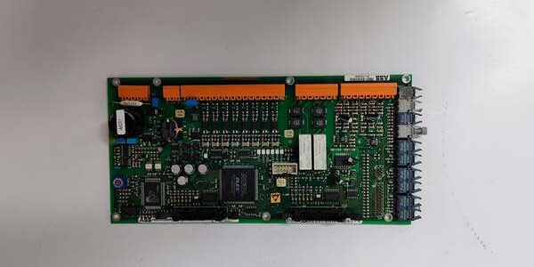
Product Core Brief
- Model: HIEE300890R0001 POS.A6092
- Brand: ABB
- Series: UNITROL 5000 Static Excitation Eurocard Subrack Hardware
- Core Function: Samples DC rotor field current via shunt signals to feed overload, loss-of-field, and thermal protection logic for synchronous generators
- Product Type: Double-width Eurocard rotor field monitoring PCB
- Key Specs: 27 V DC backplane power, 1500 V AC galvanic isolation, low-drift DC signal conditioning
- Condition: New Original (New Surplus), factory anti-static packaging, limited discontinued OEM stock
Key Technical Specifications
| Parameter | Value |
|---|---|
| Full OEM Identifier | POS. |
| Compatible Platform | UNITROL 5000 static excitation control subracks |
| Nominal Backplane Supply | 27 V DC, operating window 24 V – 30 V DC |
| Dielectric Isolation Rating | 1500 V AC between field DC shunt inputs and control logic |
| Mechanical Form Factor | Double-width Eurocard, dual rear 96-pin edge connectors |
| Measured Input Signal | 0–10 V DC proportional rotor field shunt voltage |
| Operating Cabinet Temperature | -20 °C to +60 °C non-condensing air flow |
| Storage Transit Temperature | -40 °C to +85 °C non-operating environmental range |
| Continuous Power Draw | 1.05 W under full field current signal load |
| Net Assembly Weight | 0.71 kg with all passive filter and divider components |
| Safety Compliance | IEC 61010-1 industrial power control isolation standards |
| Max Continuous Shunt Input Voltage | 10 V DC steady-state, 12 V DC transient surge tolerance |
Product Introduction
Unlike generic DC monitoring boards that introduce high thermal drift, the ABB POS. is purpose-built exclusively for UNITROL 5000 excitation systems to track rotor field DC current without measurement shift across cabinet temperature swings.This unit filters noisy shunt output signals from SCR rectifier stacks and delivers clean analog feedback to the main AVR and protection logic; its internal precision resistors limit full-scale measurement drift to 0.08% FS from -20 °C to +60 °C. It slots directly into unmodified double-width Eurocard subrack positions for hydro and turbo generator excitation retrofits and spare replacements.
Key Selling Points & Differentiators
- Quantified thermal stability: Field current measurement drift capped at 0.08% full scale across the complete rated operating temperature band, eliminating seasonal protection threshold recalibration tasks for site maintenance crews.
- Full standardized validation workflow: Every board completes a continuous 24-hour DC signal bench load test prior to shipment; digital insulation and offset test logs are provided to buyers upon formal request.
- Direct drop-in swap capability matching OEM factory wiring layouts; no secondary circuit retermination required when replacing aged rotor monitoring hardware in UNITROL 5000 racks.
- 12-month limited functional warranty covers manufacturing defects; surge damage from unfiltered rotor transients or reversed shunt wiring is excluded from coverage.
- Not recommended for UNITROL 1000 excitation hardware: Mismatched subrack pinout and power rail geometry will create permanent trace damage if force-installed into older subrack frames.
- 1500 V AC isolation barrier eliminates ground loop interference between high-current rotor shunt circuits and low-voltage subrack control logic, reducing nuisance protection trip events during grid load transients.
Mandatory Quality Transparency SOP
- Incoming Verification: Cross-reference PCB serial identifiers against ABB UNITROL factory batch records to screen counterfeit assemblies. Visual inspection checks for cracked laminate, tarnished Eurocard gold pins, swollen electrolytic filter capacitors, and missing signal range jumpers. Minor conformal coating surface discoloration does not trigger component rejection.
- Live Bench Test: Secure the PCB inside a calibrated UNITROL 5000 test subrack, supply regulated 27 V DC backplane power, and execute power-on self-checks. Inject programmable 0–10 V DC shunt simulator signals across the full measurement range for a 24-hour cyclic load cycle, logging analog offset values hourly for compliance records.
- Electrical Tests: 500 V megger insulation resistance testing across all isolation barriers; every signal-to-logic path must register above 10 MΩ. Confirm chassis protective earth continuity with a digital multimeter at the Eurocard ground terminal lug.
- Firmware Verification: This passive signal conditioning PCB carries no embedded firmware; technicians photograph front-panel signal range jumpers and attach images to unit trace documentation for field replacement reference.
- Final QC & Packaging: Fit plastic dust caps over both rear 96-pin Eurocard connectors, clean edge pins with isopropyl alcohol to remove oxidation residue, wrap the board in static-dissipative foam, seal inside rigid shock-resistant transit packaging, and affix a dated QC Passed sticker with unique technician ID number. Test photos and raw bench data files available on buyer request.
Technical Risk Avoidance Section
Firmware Mismatch Risk
Risk: UNITROL AVR logic running firmware revisions older than V4.1 cannot interpret the low-drift signal output from the ABB POS., triggering unstable thermal overload trip thresholds under variable generator field loading.Prevention: Confirm on-site UNITROL runtime firmware version before placing spare part orders; upgrade control software to V4.1 or newer if legacy code is active on the rack.Field anecdote: A 90 MW hydro generator recorded false rotor overload alarms for three weeks after fitting uncompensated monitoring boards with outdated AVR firmware.
Jumper Misconfiguration Risk
Risk: Factory jumpers are pre-set for standard 10 V full-scale shunt inputs; sites using custom 5 V shunt transformers leave jumpers unadjusted, leading to clipped signal readings and delayed rotor winding protection response.Prevention: Document on-site DC shunt voltage ratings and reposition front-panel range jumpers per the OEM datasheet before rack energization.
Terminal/Cable Incompatibility Risk
Risk: Unshielded twisted pair shunt wiring allows rectifier switching noise to bypass the PCB’s internal RC filter network, distorting field current readings and creating erratic protection logic behavior.Prevention: Deploy only shielded DC instrument cable for rotor shunt circuits; route all shield drain conductors to the cabinet master earth bar, not local subrack ground lugs.
Power Budget Miscalculation Risk
Risk: Overloading the 27 V DC subrack PSU with multiple signal and protection Eurocards drops rail voltage below 24 V DC, widening measurement error past acceptable operational limits.Prevention: Calculate total combined DC draw of all installed Eurocards and add 20% continuous power headroom to the excitation rack power supply sizing.
ESD Damage Risk
Risk: Operating environments with relative humidity below 30% generate static discharge that burns precision input divider resistors on the PCB front-end, permanently shifting field current calibration offsets with no visible physical damage.Prevention: Place an anti-static mat beneath the empty subrack during board replacement; wear a grounded ESD wrist strap when handling exposed circuit boards.
Practical summary: Complete rotor shunt wiring audit, AVR firmware version validation, and subrack power load calculation before installing the component to eliminate roughly 95% of common field failure modes.
FAQ
- Q: I maintain a UNITROL 1000 excitation rack, can this Eurocard replace my existing rotor monitoring board?A: No. The subrack backplane pin assignment and 27 V power rail layout do not match UNITROL 1000 hardware. Source the dedicated UAC387 series monitoring PCB for UNITROL 1000 deployments; forced installation will damage the component’s power input traces irreparably.
- Q: What lead time applies when ordering the ABB POS. for North American power plants?A: Stock is held at our US industrial spare parts warehouse; standard air freight delivery to domestic sites takes 3–5 business days. Sea freight shipments to Southeast Asia transit in 18–24 calendar days. OEM production of this Eurocard line is discontinued, so available inventory volume is limited.
- Q: Does the 12-month warranty cover damage caused by DC shunt short-circuit transients?A: Warranty coverage only extends to manufacturing defects within the signal conditioning circuit. Surge damage from unprotected rotor shunt wiring transients is excluded. Install DC transient suppressors on secondary shunt circuits to extend the unit’s service life.
- Q: How should I store unused spare boards long-term to avoid calibration drift?A: Keep unmounted PCBs sealed in original anti-static packaging inside a temperature-controlled storage space (15–25 °C, 40–60% RH). Avoid storage near high-current transformer cabinets that emit stray magnetic fields; these fields shift internal resistor calibration over multi-year idle periods.
- Q: Is a full generator rotor calibration run required after installing a new monitoring board?A: A no-load field current calibration test is recommended post-installation. While the board ships factory-calibrated, minor resistance differences between old and new wiring will create small signal offsets requiring trim adjustment inside the UNITROL control logic.
- Q: Can multiple of these monitoring PCBs share a single 27 V DC subrack power supply?A: Yes, but total combined continuous current draw of all Eurocards must remain under 80% of the PSU rated output. Reserve 20% load headroom to prevent voltage sag during generator transient load events.
- Q: I work at a thermal power station, what is the most frequent failure mode seen on this PCB model?A: Degraded input filter electrolytic capacitors after 7–11 years of continuous cabinet operation are the primary failure source, which increases signal noise and creates inconsistent rotor overload protection response. Inspect PCB electrolytic components during annual unit shutdowns to catch degradation before unplanned trips.





