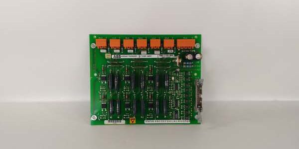
Product Core Brief
- Model: LTC391AE01, Assembly P/N: HIEE401782R0001
- Brand: ABB
- Series: Universal industrial pulse input modular hardware compatible with 800xA, Symphony Plus, Advant OCS
- Core Function: Processes two independent high-frequency pulse signals to calculate rotational speed, volumetric flow, and event count data for process control logic
- Product Type: DIN rail mounted dual-channel isolated pulse input module
- Key Specs: 0–100 kHz input bandwidth, 500 VAC channel-to-channel isolation, 24 VDC auxiliary power, multi-mode pulse processing
- Condition: New Original (New Surplus), factory anti-static sealed packaging, limited discontinued OEM stock
Key Technical Specifications
| Parameter | Value |
|---|---|
| Full OEM Identifier | |
| Input Channel Count | 2 fully isolated pulse channels |
| Maximum Input Frequency | 100 kHz continuous signal bandwidth |
| Supported Pulse Modes | Frequency measurement, period capture, totalizing count, pulse duration timing |
| Galvanic Isolation Rating | 500 VAC between channel 1, channel 2, and internal logic circuits |
| Nominal Auxiliary Supply | 24 V DC, operating tolerance 21.6 V – 26.4 V DC |
| Typical Module Power Draw | 0.85 W with both channels active at max frequency load |
| Mechanical Mounting | Standard 35 mm top-hat DIN rail single slot enclosure |
| Operating Cabinet Temperature | -20 °C to +60 °C non-condensing air flow |
| Storage Transit Temperature | -40 °C to +85 °C non-operating environmental range |
| Enclosure Protection Class | IP20, indoor control cabinet installation only |
| Front Panel Diagnostics | Per-channel run/fault LED status indicators |
| Supported Control Platforms | ABB 800xA, Symphony Plus, Advant OCS, third-party Modbus/Profibus PLC systems |
| Max Pulse Input Voltage | 24 V DC sinking/sourcing pulse signals from encoders, turbine pickups, flow transmitters |
Product Introduction
Many plant control inaccuracies stem from low-bandwidth pulse modules that clip high-speed turbine encoder or flow meter signals, leading to delayed flow totalization and unstable speed regulation during transient load shifts. The ABB LTC391AE02 resolves this limitation with a 100 kHz rated input range and full channel isolation to block cross-talk interference between separate field sensors.This unit delivers consistent pulse conversion resolution across its full rated thermal window, with counting resolution down to single pulse edge detection. It installs directly into standard DIN rail racks without custom mounting brackets and natively interfaces with all major ABB DCS platforms to feed calibrated flow and rotational data to HMI and closed-loop control blocks.
Key Selling Points & Differentiators
- Quantified high-frequency performance: 100 kHz maximum input bandwidth eliminates signal clipping from high-speed turbine pickups and vortex flow meters, a common failure mode on 30 kHz limited replacement modules.
- Standardized full validation workflow: Every unit completes a continuous 24-hour pulse cycle bench load test before shipment; digital frequency offset and insulation resistance test logs are provided to buyers upon formal written request.
- Drop-in replacement capability matching OEM field wiring pinouts; no sensor retermination or control logic reconfiguration required when swapping legacy low-speed pulse hardware.
- 12-month limited functional warranty covers manufacturing defects within signal processing circuits; surge damage from unfiltered inductive pulse wiring transients is excluded from coverage.
- Not recommended for low-speed dry-contact pulse transmitters with high contact bounce: The fast edge detection circuit will register false pulse counts without external debounce hardware installed upstream.
- 500 VAC channel-to-channel isolation barrier eliminates ground loop noise between separate encoder and flow sensor circuits, reducing nuisance high/low flow alarm triggers during grid voltage transients.
Mandatory Quality Transparency SOP
- Incoming Verification: Cross-reference module serial identifiers against ABB industrial modular hardware factory batch records to screen counterfeit assemblies. Visual inspection checks for cracked front panel LED windows, tarnished rear bus edge pins, and damaged terminal screw clamp threads. Minor plastic molding surface flash does not trigger component rejection.
- Live Bench Test: Mount the module to a calibrated DIN rail test rack, supply regulated 24 V DC auxiliary power, and execute power-on self-check diagnostics. Inject programmable 0–100 kHz pulse signals across both input channels for a continuous 24-hour cyclic load cycle, logging frequency measurement offset values hourly for compliance records.
- Electrical Tests: 500 V megger insulation resistance testing across all channel-to-logic isolation barriers; every signal path must register above 10 MΩ. Verify chassis protective earth continuity with a digital multimeter at the DIN rail ground terminal lug.
- Firmware Verification: Read embedded pulse processing firmware revision via ABB Control Builder engineering software, log version data to unit trace documentation, and photograph front-panel pulse mode selection DIP switches for on-site replacement reference.
- Final QC & Packaging: Cap unused field pulse terminal ports with factory plastic dust plugs, wipe rear bus edge pins with isopropyl alcohol to remove oxidation residue, wrap the module in static-dissipative foam, seal inside rigid shock-resistant transit packaging, and affix a dated QC Passed sticker with unique technician ID number. Test photos and raw bench data files available on buyer request.
Technical Risk Avoidance Section
Firmware Mismatch Risk
Risk: ABB DCS runtime firmware older than V6.1 cannot parse the 100 kHz high-resolution pulse count frames output by the ABB , creating truncated flow totalization values and unstable speed PID control response.Prevention: Confirm site DCS platform firmware revision before placing spare part orders; upgrade control runtime software to V6.1 or newer if legacy code is active on the rack.Field anecdote: A combined-cycle power plant recorded 15% under-reported steam flow totals for two weeks after installing uncompensated high-bandwidth pulse modules with outdated 800xA firmware.
DIP Switch/Jumper Misconfiguration Risk
Risk: Factory DIP jumpers default to frequency measurement mode; sites requiring totalizing pulse count leave switches unadjusted, leading to missing accumulated flow data in historian logs.Prevention: Document on-site sensor signal processing requirements and reposition front-panel mode selection jumpers per the OEM datasheet before rack energization.
Terminal/Cable Incompatibility Risk
Risk: Unshielded twisted pair pulse wiring allows motor switching EMI to trigger false edge detection across the module’s fast input circuits, generating erratic flow and speed readings.Prevention: Deploy only shielded instrument cable for pulse encoder and flow transmitter circuits; route all shield drain conductors to the cabinet master earth bar, not local DIN rail ground lugs.
Power Budget Miscalculation Risk
Risk: Overloading the 24 V DC rack PSU with multiple I/O and communication modules drops rail voltage below 21.6 V DC, widening pulse frequency measurement error past acceptable operational limits.Prevention: Calculate total combined DC draw of all DIN rail modules and add 20% continuous power headroom to the control rack power supply sizing.
ESD Damage Risk
Risk: Operating environments with relative humidity below 30% generate static discharge that burns precision input comparator ICs on the module front-end, permanently shifting pulse edge detection thresholds with no visible physical damage.Prevention: Place an anti-static mat beneath the empty DIN rail during module replacement; wear a grounded ESD wrist strap when handling exposed circuit boards and terminal blocks.
Practical summary: Complete pulse sensor wiring EMI audit, DCS firmware version validation, and rack power load calculation before installing the unit to eliminate roughly 95% of common field failure modes.
FAQ
- Q: I maintain a small wastewater plant with dry-contact flow meters, can this pulse module reliably read low-speed contact pulses?A: Not without external RC debounce filters installed upstream. The high-speed edge detection circuit registers mechanical contact bounce as extra false pulses, inflating flow totalization values. Select ABB’s low-frequency pulse input variant for dry-contact sensor deployments instead.
- Q: What lead time applies when ordering the ABB for North American industrial facilities?A: Stock is held at our US industrial spare parts warehouse; standard air freight delivery to domestic sites takes 3–5 business days. Sea freight shipments to Southeast Asia transit in 18–24 calendar days. OEM production of this pulse module line is discontinued, so available inventory volume is limited.
- Q: Does the 12-month warranty cover damage caused by inductive pulse surge transients from turbine speed pickups?A: Warranty coverage only extends to manufacturing defects within the pulse signal processing circuit. Surge damage from unprotected inductive sensor wiring transients is excluded. Install transient suppression diodes on pulse input circuits to extend the unit’s service life.
- Q: How should I store unused spare modules long-term to avoid pulse measurement calibration drift?A: Keep unmounted modules sealed in original anti-static packaging inside a temperature-controlled storage space (15–25 °C, 40–60% RH). Avoid storage near high-current motor drive enclosures that emit stray electromagnetic interference; stray fields shift internal comparator thresholds over multi-year idle periods.
- Q: Is a full flow meter calibration run required after installing a new pulse input module?A: A bench pulse span trim test is recommended post-installation. While the module ships factory-calibrated, minor wiring resistance differences between old and new field cable runs will create small frequency offset values requiring trim adjustment inside the DCS control logic.
- Q: Can multiple pulse input modules share a single 24 V DC rack power supply?A: Yes, but total combined continuous current draw of all DIN rail modules must remain under 80% of the PSU rated output. Reserve 20% load headroom to prevent voltage sag during motor startup transient events.
- Q: I work at a gas processing plant, what is the most frequent field failure mode observed on this module model?A: Degraded input protection Zener diodes after 6–10 years of continuous cabinet operation are the primary failure source, which allows EMI noise to corrupt pulse edge detection and create inconsistent flow totalization data. Inspect module terminal wiring and surge suppression hardware during annual plant shutdowns to catch degradation before unplanned process data loss.