
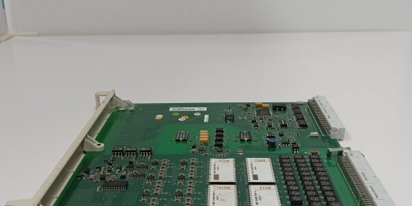
Product Core Brief
- Model: DSAI130D, OEM part number 3BSE003127R1
- Brand: ABB
- Series: S100 I/O for MasterPiece 200 safety DCS controllers
- Core Function: Convert differential field current/voltage signals to digital values for safety-critical process control loops
- Product Type: Slide-in 16-channel differential analog input rack board
- Key Specs: 16 differential input channels | 4 adjustable filter cutoff frequencies | 0.03 % full-scale static accuracy ⚠️ EOL — limited stock remaining, Condition: New Surplus
Product Introduction
ABB is a differential analog input board built for MasterPiece 200 safety control racks, engineered to suppress electrical noise from long plant sensor cabling.This unit upgrades the base DSAI130 hardware by adding four software-selectable analog filters; its tight 0.03 % FS measurement tolerance eliminates unplanned safety shutdown drift seen with standard single-ended I/O in high-CMV field environments.
Key Technical Specifications
| Parameter | Value |
|---|---|
| Channel layout | 16 fully differential analog input pairs |
| Supported field signal ranges | ±10 mA current, ±10 V voltage |
| ADC resolution | 12-bit linear conversion |
| Static full-scale measurement error | ≤ 0.03 % FS |
| Configurable filter cutoff frequencies | 10 Hz, 30 Hz, 100 Hz, 300 Hz |
| Complete board scan conversion time | 20 ms fixed cycle |
| Max continuous common mode voltage | > 50 V AC/DC |
| Backplane operating supply | 24 V DC ± 10 %, 170 mA typical draw |
| Galvanic isolation rating | 1500 VAC dielectric separation, field to rack bus |
| Operating ambient temperature | -20 °C to +60 °C full rated precision |
| Storage temperature range | -40 °C to +70 °C, 5–95 % RH non-condensing |
| Physical dimensions | W261 mm × H20 mm × D365 mm |
| Net unit mass | 0.475 kg |
| Exclusive system compatibility | MasterPiece 200 S100 safety control racks only |
Quality Control Process (Engineer’s Perspective)
- Incoming Verification: Cross-reference serial numbers against ABB S100 spare parts databases; inspect gold edge connectors for oxidation, front channel LED functionality, PCB traces for scratch damage. Validate intact OEM anti-static packaging seals to screen counterfeit surplus stock.
- Live Functional Test: Seat the unit in a S100 test rack paired with a MasterPiece 200 simulator and calibrated signal generators; run continuous 24-hour cyclic channel scanning while toggling all four filter bandwidth settings. Log stable 24 V supply and board temperature with a Fluke 115 multimeter through the full test cycle.
- Electrical Parameter Test: Use a 500 V Megger to measure field channel to backplane isolation resistance; pass threshold set above 10 MΩ. Inject 55 V common mode voltage to confirm zero measurement offset drift across all 16 differential pairs.
- Firmware Verification: No user-modifiable firmware on the unit; photograph edge connector pin labeling and document factory default 10 Hz filter configuration for commissioning reference.
- Final QC & Packaging: Wipe PCB surfaces with anti-static cloth; place the unit in foam-lined static shielding bag, attach a QC Passed label printed with inspection date before sealing in original factory carton.
Replacement Pitfall Guide
❗Firmware Mismatch Risk: MasterPiece 200 CPU firmware older than v3.11 lacks register support for multi-filter channel configuration. New board insertion triggers persistent measurement offset faults. Mitigation: Flash controller firmware to v3.11 or newer before rack installation.❗DIP Switch / Jumper Misconfiguration: The board ships with single-ended mode jumpers enabled by factory default. Differential field wiring with unadjusted jumpers yields noisy, unstable process readings. Mitigation: Photograph jumper positions on the old board and reconfigure all channel jumpers for differential operation before wiring transmitters.❗Terminal / Cable Incompatibility: Standard DSAI130 25-pin D-sub trunk cables lack shield drain pins matched to the unit’s differential front-end. Forced insertion scratches delicate signal PCB traces. Mitigation: Deploy only OEM differential trunk cables with full shield termination pins.❗Power Supply Mismatch: A single DPW03 48 W auxiliary supply cannot feed a fully populated S100 rack holding multiple of these boards. Combined continuous draw exceeds the 2 A output limit. Mitigation: Pair racks with DPW01 120 W power supplies, maintain 20 % current headroom for peak ADC sampling loads.❗ESD Damage: Dry winter control room air generates static discharge to exposed edge connector pins. Field records show ungrounded handling corrupts ADC reference circuits, creating permanent uncorrectable offset drift; full rack downtime labor costs exceed $1,600. Mitigation: Use an anti-static mat under the rack chassis and hold bare cabinet ground metal for three full seconds before seating the card into the backplane.
Keep these in mind and you’ll cut 90% of rework time.
Compatibility Matrix & Benchmarks
Compatibility Matrix
- → DSAI130 : Needs Adaptation — base model lacks adjustable noise filters, all loop logic must add digital averaging to match noise rejection performance
- MasterPiece 200 Safety CPU : Direct — native backplane register mapping, no software edits required
- Freelance 2000 DRA02 Rack : Incompatible — parallel bus pinout does not match Freelance internal rack backplane
- Two-wire differential mA transmitters : Direct — factory jumper configuration supports standard differential sensor wiring
- AC800M S800 I/O racks : Incompatible — different fieldbus and backplane communication protocols




