
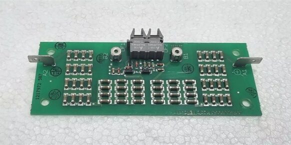
Product Core Brief
- Model: 3BHE009017R0102, alias XVC724BE VLSCD
- Brand: ABB
- Series: UNITROL 1000 static generator excitation system auxiliary communication hardware
- Core Function: Convert electrical excitation sampling signals to isolated POF fiber-optic data for AVR main controller cross-rack communication
- Product Type: Slide-in rack mount fiber interface printed circuit board
- Key Specs: Dual Versatile Link POF fiber ports | 500V channel isolation | 10Mbps optical bus throughputNote: Legacy production component, stocked inventory is New Surplus with unbroken factory anti-static packaging.
Key Technical Specifications
- Auxiliary operating supply: 24VDC ±10% rack logic feed, 130mA typical draw
- Optical media: Dual plastic optical fiber (POF) Versatile Link transceivers
- Bus data rate: Fixed 10Mbps synchronous excitation control bus
- Dielectric isolation: 500VAC separation between copper signal circuitry and fiber communication section
- Integrated circuit protection: ESD surge clamping on copper signal terminals, reverse 24VDC supply lockout
- Continuous operating temperature: -20°C to +55°C full bus load; linear performance derate above 55°C
- Storage environmental limits: -40°C to +70°C, 5%–95% relative humidity non-condensing
- Physical dimensions: 180mm L × 120mm H × 25mm D
- Net unit mass: 0.30kg
- Compliance certifications: CE, UL, RoHS, IEC 61000-6-2 Class A industrial EMC
- System compatibility: UNITROL 1010 / UNITROL 1020 excitation racks; incompatible with S800 DCS, AC800M, Advant Master, ACS variable frequency drives
Product Introduction
This fiber interface PCB translates analog generator voltage/current sampling signals into noise-immune optical data streams to eliminate ground-loop distortion across separate excitation cabinet subracks.Fiber galvanic separation blocks high-voltage switching transients from corrupting precision AVR regulation signals, cutting unplanned generator voltage oscillation trips during grid fault events.
QA & Testing SOP (Transparency Building)
- Incoming Inspection: Cross-reference serial numbers against ABB UNITROL legacy component trace logs; inspect fiber transceiver lens surfaces for scratches, copper terminal springs for tension degradation, PCB laminate for micro-cracking; verify factory static packaging seal remains intact for surplus inventory.
- Live Testing: Mount the unit to a UNITROL rack test bench paired with a generator signal simulator and matching main AVR controller; run uninterrupted 24-hour cyclic fiber bus data transmission at full 10Mbps speed; use a Fluke 115 to record steady 24VDC auxiliary supply voltage through the full test cycle.
- Electrical Testing: Perform 500VAC hipot insulation testing between all copper signal terminals and the fiber communication ground plane; pass threshold set at >10MΩ insulation resistance; inject reversed DC supply voltage to confirm hardware polarity lockout activates without damaging transceiver semiconductors.
- Firmware/Config Backup: No user-modifiable onboard firmware; photograph fiber port pin routing and terminal signal assignments to document factory wiring layouts for field commissioning reference.
- Final QC & Packaging: Torque all copper terminal screw connections to OEM torque specifications; enclose the board in static-dissipative foam; attach a printed QC tag listing serial number and completed test metrics before carton sealing.
Installation Pitfalls & Guide (Engineer to Engineer)
❗Firmware Mismatch Risk: Outdated UNITROL AVR main controller firmware lacks calibrated optical bus timing profiles for the board. Fault outcome: Intermittent loss of excitation sampling data, unstable generator terminal voltage regulation. Mitigation: Flash matching factory firmware revisions to the AVR CPU before rack power-up; archive validated firmware files to plant engineering servers.❗Fiber Cable Damage Risk: Over-bending POF fiber cables past minimum bend radius scratches internal core material. Fault outcome: Attenuated optical signals, rising bus fault counter values during peak generator load. Mitigation: Maintain a minimum 25mm fiber bend radius for all trunk runs per UNITROL cabinet wiring schematics.❗Platform Incompatibility Risk: Attempting to install the board into S800 or Advant DCS racks creates mismatched backplane pinouts and unregulated supply exposure. Fault outcome: Burned copper signal input circuits, permanent transceiver failure. Mitigation: Only deploy the board inside dedicated UNITROL 1000 series static excitation racks.❗Copper Signal Wiring Cross-Talk: Routing high-current field power cables parallel to the board’s thin sampling signal wires induces induced noise. Fault outcome: Distorted voltage/current feedback values, false over-excitation alarm triggers. Mitigation: Separate low-level sampling wiring and high-power AC/DC cabling with minimum 150mm physical spacing inside cabinet raceways.❗ESD Dangers: Low-humidity turbine control room air generates static charge that damages delicate optical transceiver ASICs on the PCB. Field records show ungrounded handling can create intermittent bus dropout faults that require 8–12 hours of diagnostic labor to isolate. Mitigation: Establish direct contact with bare cabinet chassis ground metal for three full seconds before touching fiber ports or copper terminal blocks.
4-Step Replacement Guide
- Pre-install: Lock out all rack AC auxiliary power, photograph dual POF fiber trunk routing and all generator sampling copper terminal assignments on the faulty hardware.
- Removal: Unplug both fiber connectors with gentle axial pull to avoid lens abrasion; disconnect every copper signal wire one terminal at a time and label conductors; release the rack slide latch and extract the faulty board straight outward without scraping PCB components against cabinet metal framing.
- Install: Slide the new unit evenly into the UNITROL rack slot and engage the retention latch; replicate every photographed copper terminal wiring connection to match signal channel numbering exactly, then re-seat both fiber trunk connectors fully into the transceiver ports.
- Power-on Test: Restore 24VDC auxiliary rack power (main generator field rectifier feed stays offline for initial validation); initiate continuous fiber bus polling from the UNITROL AVR controller and confirm zero communication fault counters accumulate during 30 minutes of idle sampling before energizing the main excitation power stack.
FAQ (Frequently Asked Questions)
Q: Can this board directly replace older VLSCD fiber interface hardware with different part revision suffixes?A: Yes, all revision variants share identical fiber transceiver pinouts, copper terminal signal mapping, and rack mechanical form factor. No edits to UNITROL AVR control logic or parameter sets are required for cross-revision replacement.Q: Does the hardware support hot-swapping while the UNITROL excitation rack remains energized?A: Hot-swap operation is not OEM-rated or approved. Removing the board under live power creates unfiltered sampling signal transients that trigger uncontrolled generator field current swings and risk grid voltage excursions. Full auxiliary power shutdown is mandatory for all board swaps.Q: What warranty coverage applies to surplus stocked units?A: A 12-month limited warranty only covers factory manufacturing defects. Damage from scratched fiber lenses, ESD mishandling, cross-platform rack installation, or sustained copper signal wiring short-circuits is excluded from warranty claims.Q: If one fiber transceiver port fails, can the unit remain operational with a single fiber trunk line?A: The dual fiber ports operate as a single synchronous bus link; single-port disconnection breaks the complete optical data path and cuts all sampling signal transmission to the AVR controller. Full unit replacement is required for any damaged transceiver channel.Q: Can multiple boards share a single 24VDC auxiliary power circuit in one UNITROL excitation rack?A: Multiple units may share one 24VDC supply only if the supply unit maintains 20% extra current headroom above total combined board power draw. Independent auxiliary feed wiring is recommended for racks with three or more installed units to eliminate voltage sag during peak bus data transmission cycles.Q: Is this fiber interface PCB rated for Class 1 Div 2 hazardous cabinet deployment inside gas turbine MCC rooms?A: No, the open PCB rack design lacks intrinsic safety certification for flammable vapor environments. Flameproof dedicated excitation control enclosures are required for hazardous area generator installations.Q: What long-term hardware upgrade path exists as this component reaches ABB end-of-support status?ABB’s modern UNITROL 6000 excitation platforms integrate native fiber bus transceivers directly onto the main AVR CPU board, eliminating discrete auxiliary fiber interface cards entirely. Full cabinet rack migration and control logic rework in the generator HMI layer are required for a direct functional retrofit.




