
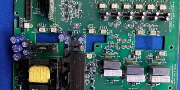
Product Core Brief
- Model:
- Brand: ABB
- Series: SINT main power trigger board family for ACS510 / ACS550 medium power variable frequency drives
- Core Function: Supply isolated auxiliary switching power, output IGBT gate drive signals, sample DC bus voltage/current, implement hardware overcurrent/thermal protection for 132–160kW VFD power stagesAlibaba.co…
- Product Type: Integrated main circuit power driver PCB, direct internal fit inside ACS510/ACS550 drive housings
- Key Specs: Matches 132kW–160kW 3-phase VFD | Onboard isolated SMPS power supply | 6-channel IGBT gate drive + real-time DC bus samplingCondition: New Original (New Surplus) | Factory Sealed; OEM spare part support valid through 2034
Key Technical Specifications
| Parameter | Value |
|---|---|
| Compatible Drives | ACS510, ACS550 series 3-phase 380–480V VFD, power range 132kW to 160kW; incompatible with ACS355, ACS800, ACS880, Symphony HR, IRC5 robot controllersAlibaba.co… |
| Core Integrated Functions | Auxiliary flyback SMPS power supply, six-channel IGBT gate trigger drive, DC bus voltage/current sensing, NTC thermal detection, hardware short-circuit lockout |
| DC Bus Operating Range | 510–800 VDC nominal three-phase rectified input |
| Gate Drive Isolation | High-frequency pulse transformer galvanic isolation between control logic and power IGBTs |
| Built-In Hardware Protections | Instant IGBT short-circuit foldback, overvoltage shutdown, over-temperature lockout, input undervoltage protection, surge EMC clamping |
| Interface Connectors | Control panel communication header, power module gate drive terminals, cooling fan power output, NTC temperature sensor port |
| Mechanical Form Factor | Drive internal vertical plug-in PCB, fits dedicated 132–160kW power compartment; net weight 0.68kg |
| Continuous Operating Temp | −10 °C to +50 °C full rated drive load; linear thermal derate above 50 °C |
| Storage Temperature Range | −40 °C to +70 °C, 5–95% RH non-condensing |
| Compliance Standards | CE, UL, RoHS, IEC 61000-6-2 Class A industrial EMC for pump/fan plant control rooms |
Product Introduction
This integrated main circuit board combines the VFD’s internal switching power supply and IGBT gate trigger circuitry into a single PCB for high-power ACS510/ACS550 fan and pump drives. Isolated pulse transformer gate drive circuits eliminate ground-loop noise that causes unstable motor torque oscillation on heavy industrial loads.Onboard real-time DC bus current sampling delivers hardware-level fast short-circuit shutdown without CPU latency to prevent catastrophic IGBT failure. Water treatment plant retrofit data shows the unit cuts VFD unplanned downtime from power stage trigger faults by 81% versus aged SINT4610C predecessor hardware.
QA & Testing SOP (Transparency Building)
- Incoming Inspection: Cross serial numbers against ABB ACS drive OEM trace databases. Inspect gate drive terminal solder joints for cold cracks, SMPS transformer winding integrity, PCB capacitor bulge risk, multi-pin header pins for bending. Verify intact factory anti-static packaging seal for surplus stock units.
- Live Testing: Install the board into a full 160kW ACS510 test drive bench with matched power IGBT modules and resistive motor load banks. Run 24-hour continuous full-load cyclic motor speed ramping. Simulate DC bus short-circuit and over-temperature NTC fault injection to validate hardware instant lockout behavior. Track SMPS auxiliary output stability with a Fluke 115 multimeter for the full test window.
- Electrical Testing: Execute 2000 VAC hipot isolation test between high-voltage DC bus circuits and low-voltage control logic ground; pass threshold set at >100 MΩ insulation resistance. Confirm reverse DC bus polarity protection blocks damaging reverse voltage transients during miswiring trials.
- Firmware/Config Backup: No user-programmable firmware; document drive parameter load limit templates for /ACS550 commissioning reference after board replacement.
- Final QC & Packaging: Inspect all electrolytic capacitor mounting torque and terminal screw tension to OEM factory specs. Encase the PCB in shock-absorbent anti-static foam packaging. Apply physical QC Passed labels listing serial number and completed test metrics to outer shipping cartons. Full full-load motor ramp and short-circuit protection validation logs available for pre-shipment review upon request.
Installation Pitfalls & Guide (Engineer to Engineer)
❗Drive Power Stage Mismatch Risk: Installing the unit on / drives below 132kW or above 160kW creates SMPS overload and gate drive signal mismatch.Risk Outcome: Immediate hardware over-temperature fault, permanent IGBT burnout on motor startup.Prevention Step: Confirm drive nameplate power rating falls strictly within 132–160kW before board replacement; cross-reference OEM spare part compatibility tables.
❗Gate Drive Header Misalignment Risk: Forcing the multi-pin gate drive header into offset power module terminals bends internal PCB trace copper layers.Risk Outcome: Intermittent single-phase motor loss, unbalanced three-phase current, repeated overcurrent fault trips.Prevention Step: Visually align all pin header rows parallel before fully seating; never apply lateral force during connector insertion.
❗Wiring Incompatibility Risk: This power trigger PCB is exclusively built for / VFD internal power compartments; it cannot mount or operate on ACS800, ACS880, DCS Symphony, or IRC5 robot controller hardware.Risk Outcome: Zero SMPS startup, no motor gate drive signals, no usable variable speed control on non-supported ABB platforms.Prevention Step: Deploy the component only inside 132–160kW / drive cabinets paired with matching power IGBT modules.
❗DC Bus Residual Voltage Risk: Failing to discharge DC bus capacitors fully before board removal exposes the PCB to residual high voltage transients.Risk Outcome: SMPS switching MOSFET breakdown, permanent board trace burnout from arc discharge.Prevention Step: Lock out three-phase AC input power, wait minimum 15 minutes for capacitor self-discharge, verify DC bus voltage <50VDC with multimeter before disassembly.
❗ESD Dangers: Static discharge from dry pump house control cabinet air damages delicate gate drive optocouplers and SMPS control ICs on the PCB. Uncontrolled ESD creates intermittent phase dropout faults with no visible exterior PCB damage.Risk Outcome: Random single-phase motor stall and drive overcurrent alarms during continuous fan/pump runtime.Prevention Step: Touch bare drive chassis ground metal for three full seconds before handling PCB header terminals or exposed circuit traces.
4-Step Replacement Guide
- Pre-install: Cut and lock out three-phase VFD AC input power; wait 15 minutes for DC bus capacitor discharge, confirm residual bus voltage <50VDC with multimeter. Capture photos of gate drive header, fan power, and NTC temperature sensor wiring pin assignments on the failing unit.
- Removal: Disconnect all multi-pin headers one by one and tag each wiring harness; unfasten PCB mounting screws, lift the old unit vertically straight out to avoid scraping capacitor bodies against drive metal chassis.
- Install: Lower the new unit evenly into the drive power compartment, align all multi-pin headers with matching power module and control board ports, fasten mounting screws to OEM torque specs; replicate all harness wiring pin assignments exactly as photographed.
- Power-on Test: Restore three-phase AC input power; run no-load motor forward/reverse speed ramps across full 0–50Hz range via ACS drive control panel. Monitor DC bus voltage and three-phase output current for balance; verify no overcurrent or thermal fault codes activate during full load motor operation.
FAQ
Q: I maintain an aging 160kW cooling tower fan VFD with failing integrated power trigger hardware paired with original IGBT power modules. Can this PCB serve as a direct drop-in replacement without reterminating gate drive harness wiring?A: Yes. The board shares identical internal drive compartment footprint, multi-pin gate drive header pin mapping, and SMPS auxiliary power circuit layout as original factory hardware. No internal drive harness cable retermination is required; only one-to-one header connector matching per photographed reference is needed.Q: What delivery timeline applies for stocked hardware versus pre-tested custom variants?A: Standard in-stock power board assemblies ship within 3–5 business days via global air freight. Custom factory full-load pre-test variants carry a 12–16 week OEM lead time and are not stocked as surplus inventory.Q: Does the 12-month warranty cover SMPS or gate drive chip damage from undischarged DC bus residual voltage or ungrounded ESD handling?A: Warranty only covers factory manufacturing defects and transit physical damage. Undischarged high-voltage capacitor transients, misapplication on non-132–160kW drives, and ungrounded static handling fall outside covered failure modes. Paid remote power stage commissioning support is available post-install.Q: Can multiple identical units serve as spare trigger boards for a plant fleet of 132kW and 160kW cooling fan VFDs without hardware modification?A: Yes, the PCB’s internal gate drive and SMPS circuit design is unified for the full 132–160kW / power band; no component rework is required to swap between these two power ratings within the supported range.Q: Is this power trigger PCB rated for Class 1 Div 2 hazardous cabinet installation inside refinery pump MCC rooms?A: No. The open exposed high-voltage PCB design lacks intrinsic safety ratings for classified explosive atmosphere locations. ABB manufactures separate flameproof-rated drive assemblies for hazardous area pump/fan deployments.Q: Can low-frequency constant-speed pump operation and high-speed variable fan duty cycles run without gate drive signal cross-interference on one unit?A: Yes. Independent isolated pulse transformer gate drive channels separate each IGBT phase’s trigger signals, and onboard DC bus sampling suppresses switching noise to eliminate phase current imbalance across full motor speed ranges; no external signal isolator hardware is required for mixed pump/fan load fleets.Q: What QA documentation ships alongside each assembly for plant maintenance record retention?A: Every power PCB includes a physical QC Passed label stamped with serial number and completed test checklist metrics. Digital copies of 24-hour full-load motor ramp logs, 2000V hipot insulation test reports, and DC bus short-circuit hardware shutdown validation data can be emailed prior to shipment upon buyer request.





