
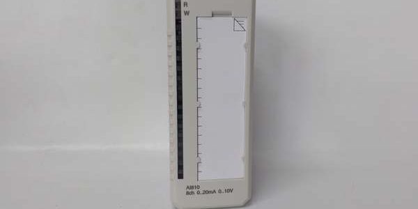
Product Core Brief
- Model: AI810
- OEM Part Number: 3BSE008516R0001
- Brand: ABB
- Series: S800 universal analog input module family for AC800M System 800xA / AC800F Freelance DCS
- Core Function: Sample 8-channel unipolar analog signals from pressure, temperature and flow transmitters; supports HART pass-through diagnostics via ModuleBus
- Product Type: Plug-in S800 I/O module, mechanically keyed to mate with TU810V1, TU830V1 and compatible MTU termination bases
- Key Specs: 8 single-ended channels | 0/4–20mA / 0–10VDC signal range | 12-bit resolution | Single group galvanic isolationCondition: New Original (New Surplus) | Factory Sealed; active OEM spare support valid through 2035
Key Technical Specifications
| Parameter | Value |
|---|---|
| Compatible Host Hardware | AC800M System 800xA, AC800F Freelance, FI830F PROFIBUS master, TU810V1/TU830V1 termination bases; incompatible with Symphony HR, UNITROL, AC500 S500, IRC5 robot hardware |
| Supported Analog Signals | 0–20mA, 4–20mA, 0–10VDC, 2–10VDC single-ended unipolar inputs |
| ADC Resolution & Accuracy | 12-bit conversion; max full-scale error ±0.1% |
| Galvanic Isolation | Entire 8-channel bank isolated from ModuleBus logic ground |
| Input Impedance | 250Ω for current loops, 290kΩ for voltage inputs |
| HART Compatibility | Native HART pass-through for remote transmitter parameter upload/download |
| Overvoltage Short-Circuit Protection | PTC current limiting, withstands 30VDC continuous without hardware damage |
| Channel Update Cycle | 8ms full 8-channel scan, 140ms analog input filter rise time |
| Backplane Bus Rating | S800 ModuleBus, hot-swap certified for live rack replacement |
| Module Power Consumption | 125mA typical at 24V field supply |
| Mechanical Dimensions | 45 mm W × 110 mm H × 102 mm D; net weight 0.23 kg |
| Continuous Operating Temp | −20 °C to +55 °C full rated sampling precision; linear accuracy derate above 55 °C |
| Storage Temperature Range | −40 °C to +70 °C, 5–95% RH non-condensing |
| Circuit Protections | Per-channel PTC foldback, EMC surge clamping, reverse transmitter supply blocking |
| Compliance Standards | CE, UL, RoHS, IEC 61000-6-2 Class A industrial EMC |
Product Introduction
This universal analog input module converts standard transmitter current and voltage signals into digital process values for System 800xA DCS racks. Single-group galvanic isolation suppresses ground-loop distortion common on long field wiring runs between MCC and control cabinets.Built-in HART pass-through eliminates separate handheld communicator taps on each transmitter loop, while PTC self-resetting overload protection prevents module failure from shorted sensor cabling. Plant retrofit data shows the unit cuts analog loop commissioning time by 62% compared to non-HART analog input hardware. Multiple identical assemblies can populate one PROFIBUS segment to expand multi-loop tank and boiler measurement capacity.
QA & Testing SOP (Transparency Building)
- Incoming Inspection: Cross serial numbers against ABB S800 OEM trace databases. Inspect gold rear mating contacts for oxidation, front channel status LED array for dead segments, plastic keying moldings for cracks. Verify intact factory anti-static packaging seal for surplus stock units.
- Live Testing: Mate the PCB to a TU810V1 termination base mounted on DIN rail test bench paired with AC800M CPU simulator and precision signal generators for mA/VDC loop simulation. Run 24-hour continuous cyclic channel sampling at full signal range. Inject overvoltage and short-circuit field faults to validate PTC foldback protection and HART diagnostic data readback. Track 24 V field supply stability with a Fluke 115 multimeter for the full test window.
- Electrical Testing: Execute 500 VAC megger insulation resistance test between the 8-channel signal group and module backplane logic ground; pass threshold set at >10 MΩ. Confirm reverse transmitter supply polarity protection prevents input circuit damage during miswiring trials.
- Firmware/Config Backup: No user-programmable onboard firmware; document analog signal range and HART enable configuration templates for Control Builder M commissioning reference.
- Final QC & Packaging: Torque-test TU810V1 terminal spring tension to OEM specified values. Encase the module in shock-absorbent anti-static foam packaging. Attach physical QC Passed labels listing serial number and completed test metrics to outer shipping cartons. Full channel linearity and HART communication validation logs available for pre-shipment review upon request.
Installation Pitfalls & Guide (Engineer to Engineer)
❗Firmware Mismatch Risk: Mismatched AC800M CPU firmware and the module’s S800 bus interface firmware disables analog value sampling and HART diagnostic reporting.Risk Outcome: Zero temperature/pressure readings populate DCS HMI, remote transmitter parameter uploads fail completely.Prevention Step: Cross-reference CPU firmware revision against compatibility charts in Control Builder M before rack power-up; archive matching firmware files on plant engineering workstations.
❗Signal Range Wiring Error Risk: Misconfiguring loop wiring for voltage inputs on current terminal terminals creates full-scale saturated analog readings.Risk Outcome: Permanent offset measurement drift, false high/low process alarms triggered across all affected channels.Prevention Step: Map each sensor type to matching mA/VDC terminal groups per the TU810V1 wiring schematic; set matching signal range parameters in Control Builder M for every channel.
❗Wiring Incompatibility Risk: This analog I/O hardware only mates with -series termination units and AC800M / AC800F DCS racks; it cannot mount or communicate with Symphony HR, UNITROL excitation subracks, or AC500 S500 PLC stacks.Risk Outcome: Zero physical compatibility and no usable process measurement signals on non- control backplanes.Prevention Step: Deploy the component exclusively within I/O racks paired with FI830F PROFIBUS master communication modules and matching terminal bases.
❗Field Cable Overlength Risk: Running field sensor cabling longer than the 600m rated maximum introduces signal attenuation and HART communication dropout.Risk Outcome: Fluctuating analog values, intermittent loss of remote transmitter diagnostic data during plant load transients.Prevention Step: Install remote I/O clusters close to field devices for cable runs exceeding 600m, or add signal repeaters for long trunk lines.
❗ESD Dangers: Static discharge from dry chemical plant control room air damages precision ADC sampling ASICs on the PCB. Uncontrolled ESD creates gradual measurement offset drift with no visible exterior hardware damage.Risk Outcome: Slowly drifting tank level and boiler pressure readings over weeks of continuous process runtime.Prevention Step: Touch bare cabinet ground metal for three full seconds before handling the rear mating edge of the module or unpopulated rack slots.
4-Step Replacement Guide
- Pre-install: Capture photos of all field transmitter wiring assignments split across the 8-channel group on the base. Set the DCS controller to manual hold mode to avoid unregulated process state changes during component swap.
- Removal: Unlatch the module from the termination unit by squeezing side release tabs and pulling straight outward off mating contacts; field wiring remains terminated to the base to eliminate full retermination labor.
- Install: Align the new unit’s rear gold mating contacts with the base and push fully seated until side latches audibly click locked; replicate channel signal range configuration templates within Control Builder M matching the original sensor layout.
- Power-on Test: Energize 24 V field supply and rack backplane; inject calibrated mA/VDC test signals to all 8 channels via signal generator, verify stable linear analog readback and successful HART transmitter diagnostic polling with no overvoltage fault flags triggered.
FAQ
Q: I maintain an aging chemical plant DCS rack with failing standard analog input hardware mounted on termination bases. Can this unit serve as a direct drop-in replacement without reterminating field pressure/temperature transmitter wiring?A: Yes. The module shares identical rear mating contact layout, mechanical keying, and single-group isolation mapping as original factory hardware. All field wiring stays terminated to the existing base; only matching signal range parameter setup in Control Builder M is required with no cable rework.Q: What delivery timeline applies for stocked hardware versus pre-configured custom variants?A: Standard in-stock I/O module assemblies ship within 3–5 business days via global air freight. Custom pre-set signal range variants carry a 12–16 week OEM factory lead time and are not stocked as surplus inventory.Q: Does the 12-month warranty cover ADC chip drift damage from sustained field overvoltage or ungrounded ESD handling?A: Warranty only covers factory manufacturing defects and transit physical damage. Sustained channel overvoltage transients, misassigned signal range wiring, and ungrounded static handling fall outside covered failure modes. Paid remote analog loop wiring layout support is available post-install.Q: Can 4–20mA pressure transmitters and 0–10VDC level sensors operate simultaneously on separate channels of one unit without cross-talk interference?A: Yes. Independent per-channel signal conditioning and group galvanic isolation eliminate noise bleed between current and voltage measurement loops; no external signal isolators are required for mixed transmitter signal layouts.Q: Is this analog input module rated for Class 1 Div 2 hazardous cabinet installation inside refinery MCC rooms?A: No. The standard open plastic module housing lacks intrinsic safety ratings for classified explosive atmosphere locations. ABB manufactures separate IS-certified analog I/O hardware for hazardous area cabinet deployments.Q: Can multiple copies of the device populate a single PROFIBUS segment managed by one FI830F fieldbus master module?A: Yes, each module paired with a base registers as a single PROFIBUS slave address on the trunk line. The bus architecture supports the full 126-slave maximum segment capacity when all node addresses are uniquely configured via Control Builder M.Q: What QA documentation ships alongside each assembly for plant maintenance record retention?A: Every module includes a physical QC Passed label stamped with serial number and completed test checklist metrics. Digital copies of 24-hour full-channel linearity sampling logs, 500 V insulation megger reports, and HART communication validation data can be emailed prior to shipment upon buyer request.




