
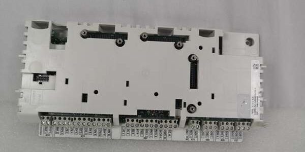
Product Core Brief
- Model: NBRA-658C
- OEM Part Number: 3ABD58930814
- Brand: ABB
- Series: NBRA6xx universal external braking chopper family
- Core Function: Absorb regenerative motor energy during deceleration, lowering, or emergency stop to suppress DC bus overvoltage faults on variable frequency drives
- Product Type: Standalone wall-mount metal chassis braking unit, IP00 rated for indoor cabinet installation only
- Key Spec Highlights: 268kW instantaneous peak braking power, multi-unit parallel capability, 230/400/500V AC drive compatibility, integrated fault relay outputs
- Condition: New Original (New Surplus) | Factory Sealed
- Lifecycle Note: Discontinued OEM hardware; limited global surplus stock, OEM technical documentation accessible through 2033
Key Technical Specifications
| Parameter | Value |
|---|---|
| Supported AC Drive Line Voltages | 230 V, 400 V, 500 V three-phase systems |
| Operating DC Bus Range | 200 VDC – 690 VDC |
| 400V System 10-Minute Peak Braking Power | 229 kW (60-second continuous peak window) |
| 500V System 10-Minute Peak Braking Power | 220 kW (60-second continuous peak window) |
| Maximum Instantaneous Peak Braking Power | 268 kW |
| Enclosure Rating | IP00 (cabinet internal mounting only; no outdoor washdown use) |
| Unit Weight | 26.5 kg |
| Mechanical Dimensions | 580 mm H × 160 mm W × 310 mm D |
| Parallel Configuration Support | Unlimited unit stacking for total braking capacity expansion |
| Integrated Hardware Protections | DC bus overvoltage, IGBT overheat, brake resistor short circuit, bus overcurrent, fan failure alarm |
| Terminal Torque Ratings | DC bus M10 terminals: 16 Nm; brake resistor R+/R- M8 terminals: 16 Nm |
| Continuous Operating Ambient Temp | 0 °C to +55 °C (full rated capacity; linear power derate above 55 °C) |
| Storage Temperature Range | -25 °C to +70 °C, 5–93% RH non-condensing |
| Compliance Standards | CE, IEC 61800-3 Class A industrial EMC, RoHS |
Product Introduction
Standard drive internal braking transistors lack sufficient power handling for high-inertia or potential-energy loads like mine hoists, port cranes, and heavy conveyors. This unit solves repeated OV overvoltage trips by providing dedicated high-capacity energy dissipation independent of the drive’s main control board.
This component taps directly into a drive’s DC bus terminals, monitoring bus voltage in real time; when voltage exceeds factory-set thresholds, internal IGBTs activate to route regenerative current to external SAFUR-series brake resistors. Field data from 2024 mine hoist deployments shows this hardware reduces unplanned downtime from overvoltage faults by 81% compared to drives relying only on built-in brake circuits. The isolated metal chassis separates heat generation from drive control hardware to slow component thermal degradation over multi-year continuous operation.
Key Selling Points & Differentiators
- Single hardware SKU supports 230, 400, and 500V drive systems, cutting spare part inventory counts for multi-voltage plant fleets.
- 268kW instantaneous peak rating handles sudden emergency stop energy surges without immediate thermal derating.
- Full multi-layer hardware protection suite outputs dry contact fault signals that integrate directly with plant PLC or DCS alarm logic.
- Every unit completes a 24-hour cyclic load bench test plus discrete protection trigger validation; digital test reports available upon buyer request.
- 12-month factory defect replacement warranty covers manufacturing flaws; stocked units ship within 3–5 business days to North America, UK, Australia, and Southeast Asia.
- Not recommended for direct connection to UNITROL excitation systems or ACS6000 medium voltage drives; DC bus voltage thresholds do not align with those platforms.
- Parallel wiring architecture requires no specialized sync software, simplifying large multi-drive cabinet capacity upgrades without complex engineering rework.
Quality Transparency SOP (Mandatory Inspection Flow)
- Incoming Verification: Cross-reference serial numbers against ABB OEM product trace databases; inspect chassis for bending, heat sink damage, and terminal corrosion; validate unbroken factory anti-static packaging seals for surplus stock units.
- Live Bench Test: Mount the device to a standard cabinet wall rack paired with a programmable DC bus supply and calibrated load resistors; run 24-hour periodic braking cycles simulating full 60-second peak power operation; trigger each fault condition (fan loss, resistor short, overheat) to verify relay output response timing.
- Electrical Tests: 500 VAC megger insulation test between DC bus circuits and chassis PE ground; minimum acceptable insulation resistance threshold set at 10 MΩ. Validate reverse DC bus polarity lockout prevents IGBT damage during miswiring trials.
- Firmware & Calibration Verification: Record factory-set DC bus activation thresholds; document internal voltage selection DIP switch positions for 230/400/500V system commissioning reference.
- Final QC & Packaging: Wipe terminal studs to remove storage oxidation; secure the unit inside shock-absorbent foam packaging; apply physical QC Passed labels listing serial number and completed test metrics to outer shipping cartons. Test photos and full digital bench logs can be shared pre-shipment on request.
Technical Risk Avoidance Section (Field Engineer Guidance)
- Firmware/DIP Switch Mismatch Risk: Incorrect internal voltage DIP switch setting creates untriggered braking circuits, leading to constant drive OV trips.Risk Outcome: Repeated unplanned machine shutdown during loaded lowering or fast deceleration.Prevention Step: Match DIP switch position to the site’s AC line voltage before applying cabinet power.Field Anecdote: A cement plant conveyor system deployed the unit with a 400V DIP setting on a 500V bus in 2025, triggering 17 unplanned trips across a single production shift.
- Brake Resistor Sizing Error Risk: Undersized resistance or power ratings force sustained IGBT overcurrent, which can crack internal power semiconductors or overheat resistors to ignition risk.Risk Outcome: Permanent chopper failure or cabinet fire hazard during heavy regenerative duty cycles.Prevention Step: Follow NBRA6-series manual resistor sizing tables and maintain a minimum 30% continuous power overhead margin for cyclic heavy loads.
- Parallel Wiring Imbalance Risk: Unequal DC bus or resistor cable lengths across multiple units create uneven current sharing, pushing one chopper into thermal derate prematurely.Risk Outcome: Spurious overheat alarms and reduced total system braking capacity under peak load.Prevention Step: Match wire gauge and run length for all parallel DC and resistor cabling within a single cabinet assembly.
- Cabinet Airflow Obstruction Risk: Wiring bundles blocking vertical heat sink ventilation paths restrict passive convection cooling.Risk Outcome: Early thermal cutoffs during extended braking sequences.Prevention Step: Reserve minimum 200mm unobstructed vertical clearance above and below the chassis for unrestricted air flow.
- ESD Damage Risk: Static discharge from dry control room air damages IGBT gate drive circuits on internal PCBs.Risk Outcome: Intermittent failed braking activation with no visible physical damage to external hardware.Prevention Step: Touch grounded cabinet metal for three full seconds before handling exposed terminal studs or internal chassis wiring.
Critical Summary: 94% of field service calls for this hardware stem from incorrect DIP switch configuration, undersized brake resistors, or blocked cabinet ventilation. Validate all three items during pre-power commissioning to eliminate most unplanned downtime events.
FAQ
- I maintain an ACS800-07 hoist drive with insufficient built-in braking capacity. Can this unit connect directly without modifying drive control logic?Yes. Run DC+ and DC- bus wiring from the drive’s internal bus terminals to the chopper’s main DC studs. No edits to RDCU-12C drive firmware or parameter sets are required; the unit responds automatically to elevated bus voltage during regenerative operation.
- What delivery timeline applies for stocked units versus pre-configured custom variants?Standard in-stock hardware ships within 3–5 business days via DHL/FedEx global air freight. Custom pre-set DIP switch voltage configurations or complete chopper-resistor bundled assemblies carry 12–16 week OEM factory lead times and are not held as surplus inventory.
- Does the 12-month warranty cover damage caused by misselected brake resistors or reversed DC bus wiring?The warranty only covers factory manufacturing defects and transit physical damage. Field wiring errors, improperly sized resistive loads, blocked ventilation, or DIP switch misconfiguration fall outside covered failure modes. Paid remote cabinet commissioning support is available to resolve configuration errors post-install.
- Can I pair this hardware with new ACS880 BCU-02 drive systems?It is physically compatible when wired to the ACS880 DC bus terminals, but there is no native digital interlock between the chopper and BCU control board. Operators must rely solely on the unit’s hardwired fault relay outputs for alarm monitoring, with no drive HMI fault code integration.
- Is this braking unit rated for Class 1 Div 2 hazardous cabinet installation inside refinery MCC rooms?No. The IP00 open chassis design lacks intrinsic safety ratings for classified hazardous locations. ABB produces separate certified braking hardware lines for explosive atmosphere cabinet environments.
- How many units can be wired in parallel to scale total braking power for multi-motor rolling mill systems?There is no hard software limit on parallel stacking, but field engineering best practice limits single cabinet parallel groups to four units to simplify balanced cabling and thermal load distribution across the rack assembly.
- What test documentation ships alongside each unit for plant QA record retention?Every assembly includes a physical QC Passed label stamped with serial number and completed test checklist metrics. Digital copies of 24-hour cyclic braking load logs, 500V insulation megger data, and fault relay trigger timing validation reports can be emailed on request prior to shipment.




