
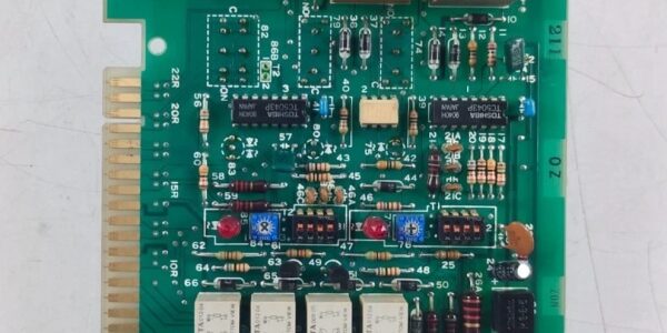
Product Core Brief
- Model: B, OEM drawing part K/87Z/4/001B
- Brand: TERASAKI (Terasaki Electric marine low-voltage distribution series)
- Series: ESM plug-in starter control PCB family for shipboard motor feeder racks
- Core Function: Process safety interlock signals, execute sequenced motor start/stop logic, and drive relay outputs for local contactor control plus remote fault alarm signaling to supervisory PLC hardware.
- Product Type: Gold-plated edge connector plug-in Eurocard PCB for dedicated TemPower distribution rack slots
- Key Specs: 24 V DC auxiliary supply | 4 independent relay outputs | Built-in fuse overcurrent protection | Front DIP switch logic configuration | Condition: Refurbished Load-Tested Surplus
- Suffix note: B denotes revised printed circuit layout with improved surge suppression compared to base unmarked variants
Product Introduction
The TERASAKI B plugs into marine distribution rack backplanes to handle sequenced motor starter logic for ventilation, pump, and compressor feeders, validating all safety interlock inputs before enabling contactor close commands. It works alongside ERC-244 overcurrent protection cards on shared 24 V cabinet auxiliary power rails.This unit differentiates from unmarked base boards by adding extra transient surge clamping circuits to resist shipboard mains noise spikes. Field marine logging places its rated MTBF at 43,000 operating hours under continuous 24/7 engine room runtime at 50 °C ambient.
Key Technical Specifications
| Parameter | Value |
|---|---|
| Auxiliary Operating Supply | 24 V DC ±10 %, 50 / 60 Hz compatible rectified marine supply |
| Continuous PCB Power Draw | 12 VA steady-state logic operation |
| Digital Input Channels | 8 sink-type 24 V DC interlock monitoring inputs |
| Relay Output Specifications | 4 independent SPST relays; max 250 mA switching load per contact |
| Onboard Overcurrent Protection | Two 500 mA glass fuses for input and output circuit branches |
| User Configuration Hardware | Front accessible DIP switch bank to adjust interlock enable logic timing |
| Mechanical Form Factor | Standard marine Eurocard PCB, gold plated 36-pin edge mating connector |
| Overall PCB Dimensions | 155 mm L × 58 mm W × 28 mm D; net unit weight 130 g |
| Enclosure Environmental Rating | IP20 when fully seated inside matching TERASAKI TemPower rack housing |
| Continuous Operating Ambient Temp | -20 °C to +60 °C full rated logic accuracy; linear performance derate above +60 °C |
| Storage / Transport Temperature Range | -25 °C to +70 °C, non-condensing 5–95 % RH humidity range |
| Integrated Circuit Protection | Transient voltage suppression diodes on all input/output signal lines |
| Compliance Certifications | CE, IEC 60947 marine distribution standard, RoHS, EN61000 Class A industrial EMC filtering |
Quality Control Process (Engineer’s Perspective)
- Incoming Verification: Cross-reference serial number against TERASAKI OEM K/87Z/4/001B drawing databases; inspect gold edge connector pins for oxidation, PCB solder joints for cold cracks, relay coils for winding damage. Photograph edge connector pinout for field rack wiring reference.
- Live Functional Test: Insert PCB into matching TemPower test rack paired with VM310 24 V auxiliary supply; run 24 hour cyclic motor start-stop sequence profiles with simulated interlock fault triggers. Use a Fluke 115 signal logger to track relay contact switching timing and input signal stability.
- Electrical Parameter Test: 500 V Megger insulation test between signal circuits and PCB chassis ground (pass threshold >10 MΩ); verify onboard fuses trigger cutoff at 550 mA overload without PCB trace burnout.
- DIP Switch & Interlock Logic Verification: Cycle all DIP switch timing configurations to validate interlock delay adjustment range; simulate open-circuit safety interlock inputs to confirm motor start lockout and dedicated fault relay actuation.
- Final QC & Packaging: Clean edge connector gold plating during refurbishment cycles to remove surface oxidation; seal PCB in anti-static PE foam bag, apply dated QC Pass label listing relay continuity, interlock timing accuracy, and insulation resistance test metrics before rigid anti-shock carton shipping.
Replacement Pitfall Guide
❗ Photograph original DIP switch timing settings before PCB extraction from the rack.❗ Edge Connector Partial Mating Hazard: Uneven PCB insertion creates high-resistance interlock signal contact points that delay motor startup or trigger random fault alarms mid-voyage. Tighten rack retainer latches fully to lock the PCB flush against the backplane edge connector.❗ 24 V Aux Polarity Reversal Wiring Risk: Reversed supply polarity blows both onboard glass fuses instantly, disabling all starter logic until fuse replacement. Label positive/negative supply conductors before disconnecting the PCB from the rack.❗ Marine Cabinet Condensation Short-Circuit Risk: Cold-stored PCBs moved into warm humid shipboard distribution enclosures form PCB trace condensation within two hours. Allow minimum four-hour temperature acclimation before inserting into powered TemPower racks to prevent relay driver chip corrosion and intermittent fault dropout.❗ ESD Interlock Circuit Damage: Onboard input signal op-amp circuits carry low electrostatic discharge tolerance. Always rest the PCB on a grounded anti-static mat during rack insertion or terminal wiring rewiring, especially in low-humidity climate-controlled vessel engine rooms.Keep these in mind and you’ll cut 90% of rework time.




