
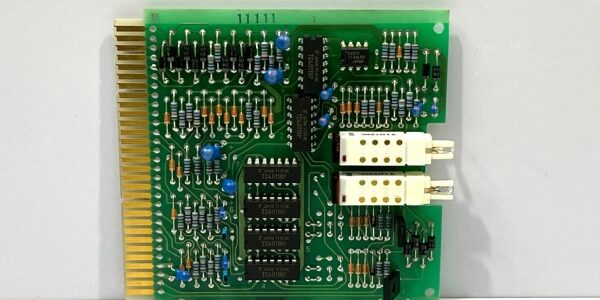
Product Core Brief
- Model: ERC-244, OEM drawing reference K/751/119-002A
- Brand: TERASAKI (Terasaki Electric, Japan marine & industrial low-voltage specialist)
- Series: ERC plug-in electronic protection PCB family for air circuit breaker frames
- Core Function: Monitor 3-phase motor and feeder current signals, execute programmable overload, short-circuit, and phase-loss protection, output fault relay triggers to main breaker trip coils and supervisory PLCs.
- Product Type: Edge-connector plug-in PCB control card, fits standard TERASAKI TemPower 2 rack slots
- Key Specs: 24–240 V universal AC/DC auxiliary supply | Multi-step adjustable trip curves | LED fault status indicators | IP20 internal chassis rating | Condition: Refurbished Load-Tested Surplus
- Board note: This plug-in PCB only operates when installed inside matching TERASAKI ACB distribution frames; standalone power-up will trigger permanent fault lockout.
Product Introduction
The TERASAKI plugs into TemPower 2 air circuit breaker racks to deliver solid-state overcurrent protection for marine vessel distribution feeders and industrial motor loads, processing CT current signals to calculate thermal motor loading without mechanical thermal elements.This unit differentiates from older ERC-232N single-function cards by adding phase-loss detection and four independent fault relay outputs for remote alarm signaling. Field OEM marine logging lists its rated MTBF at 45,000 operating hours under continuous 24/7 shipboard cabinet runtime at 50 °C ambient.
Key Technical Specifications
| Parameter | Value |
|---|---|
| Auxiliary Control Supply | 24 V to 240 V AC / DC universal input, 50 / 60 Hz |
| Continuous Auxiliary Power Draw | 12 VA steady-state operation |
| Current Sensing Input | Compatible with standard distribution CT secondary 1 A / 5 A signals |
| Configurable Protection Curves | Long-time overload, short-time delay, instantaneous short-circuit, phase-loss trip |
| Fault Output Interfaces | Four isolated relay contact outputs; max 2 A switching capacity per contact |
| Diagnostic Indicators | Front PCB bank of status LEDs for normal run, overload pre-alarm, short-circuit trip, phase loss |
| Mechanical Form Factor | Standard plug-in Eurocard PCB, gold-plated edge connector pins for rack mating |
| Overall PCB Dimensions | 263 mm L × 58 mm W × 28 mm D; net unit weight 90 g |
| Enclosure Environmental Rating | IP20 when fully inserted into TERASAKI ACB chassis |
| Continuous Operating Ambient Temp | -20 °C to +60 °C full rated protection accuracy; linear derate above +60 °C |
| Storage / Transport Temperature | -25 °C to +70 °C, non-condensing 5–95 % RH humidity range |
| Built-In Circuit Protection | Onboard fuse for auxiliary supply reverse polarity, CT open-circuit blocking clamp circuits |
| Compliance Certifications | CE, IEC 60947-2 marine distribution standard, RoHS, EN61000 Class A EMC filtering |
Quality Control Process (Engineer’s Perspective)
- Incoming Verification: Cross-reference serial number against TERASAKI OEM K/751/119-002A drawing databases; inspect gold edge connector pins for oxidation, PCB solder joints for cold cracks, LED indicator diodes for dead segments. Photograph edge connector pinout for field ACB rack wiring reference.
- Live Functional Test: Insert PCB into matching TemPower 2 test chassis paired with variable CT signal simulator and 110 V AC auxiliary supply; run 24 hour cyclic overload and short-circuit profile tests. Use a Fluke 115 signal logger to track relay output switching timing and LED trigger threshold consistency.
- Electrical Parameter Test: 500 V Megger insulation test between CT sensing circuits and PCB chassis ground (pass threshold >10 MΩ); verify auxiliary supply reverse-polarity fuse trips at over 260 V input overvoltage.
- Trip Curve & Fault Logic Verification: Adjust onboard DIP switch banks to cycle all four protection curve settings; simulate CT open-circuit and single-phase loss conditions to confirm dedicated fault LED illumination and corresponding relay contact actuation.
- Final QC & Packaging: Clean edge connector gold plating during refurbishment cycles to remove surface oxidation; seal PCB in anti-static PE foam bag, apply dated QC Pass label listing trip curve accuracy, relay contact continuity, and insulation resistance test metrics before rigid anti-shock carton shipping.
Replacement Pitfall Guide
❗ Photograph original DIP switch trip curve settings before PCB extraction from the ACB rack.❗ Edge Connector Partial Mating Hazard: Uneven PCB insertion creates high-resistance CT signal contact points that skew overload current calculations. Poor seating generates false overload pre-alarms mid-voyage or factory production batches. Tighten rack retainer latches fully to lock the PCB flush against the backplane edge connector.❗ ❗ Marine Cabinet Condensation Short-Circuit Risk: Cold-stored PCBs moved into warm humid shipboard distribution enclosures form PCB trace condensation within two hours. Allow minimum four-hour temperature acclimation before inserting into powered ACB racks to prevent relay driver chip corrosion and intermittent fault dropout.❗ ESD Sensing Circuit Damage: Onboard CT signal op-amp circuits carry low electrostatic discharge tolerance. Always rest the PCB on a grounded anti-static mat during rack insertion or terminal wiring rewiring, especially in low-humidity climate-controlled vessel engine rooms.Keep these in mind and you’ll cut 90% of rework time.
Compatibility Matrix & Benchmarks
Compatibility Matrix
- ERC-232N legacy protection PCB → : Needs Adaptation — rewire two additional fault relay interlock circuits, reconfigure ACB supervisory PLC logic to accept phase-loss alarm signals
- TERASAKI TemPower 2 air circuit breaker chassis → : Direct — factory backplane edge connector pinout natively matches PCB sensing, auxiliary power, and fault relay signal routing
- VM310 24 V cabinet auxiliary power supply → : Direct — regulated 24 V DC auxiliary output meets PCB universal supply input requirements without voltage conditioning
- CML40.2-SP-330-NA-NNNN-NW SERCOS motion PLC → : Direct — fault relay dry contacts wire directly to PLC 24 V digital input channels for distribution system fault trending




