
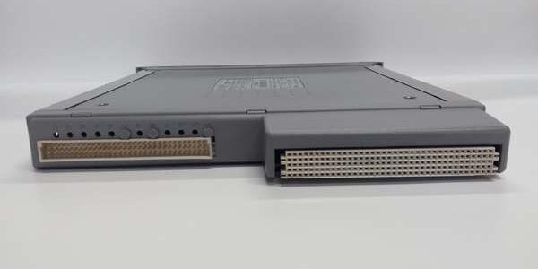
Product Core Brief
- Model: T8461
- Brand: ICS Triplex (Rockwell Automation)
- Series: Trusted TMR Safety Control Series ⚠️ EOL — limited new surplus stock remaining
- Core Function: Deliver triplicated digital output signals to solenoids and shutdown valves via 2oo3 hardware voting; supports both 24 VDC and 48 VDC field actuator wiring
- Product Type: Backplane-mount TMR dual-voltage digital output I/O module
- Key Specs: 40 triplicated output channels | 0.75 A continuous per channel | Dual 24/48 VDC field voltage support | Native SmartSlot interface for T8850 FTA | Condition: New Original Surplus
Product Introduction
The ICS Triplex is a single-slot TMR digital output card built for flexible mixed-voltage SIS and ESD systems, using three parallel voted circuit paths to eliminate single-point channel failures. It pairs exclusively with the T8850 mixed-signal output FTA to separate rack backplane wiring from live field actuator cabling.This module differs from the T8451 single-voltage variant with native 48 VDC field load compatibility and expanded 18–60 VDC field surge withstand. OEM reliability testing records an MTBF of 115,000 operating hours at a steady 40 °C cabinet ambient.
Key Technical Specifications
| Parameter | Value |
|---|---|
| Total Output Channels | 40 fully triplicated TMR digital output channels |
| Channel Power Grouping | 5 isolated banks of 8 channels each, galvanically separated |
| System Backplane Supply | 20 VDC to 32 VDC nominal 24 VDC |
| Supported Field Operating Voltage | 18 VDC to 60 VDC (24 VDC / 48 VDC nominal field circuits) |
| Per-Channel Continuous Current | 0.75 A max; 6 A aggregate per isolated power group |
| Overcurrent Protection | Latching electronic cutoff per channel, auto-reset post fault clearance |
| Event Logging Resolution | 1 ms Sequence of Events (SOE) timestamping for channel state and fault transients |
| Galvanic Isolation Rating | 2500 V impulse withstand channel-to-backplane barrier |
| Backplane Interface | SmartSlot gold edge connector for T8850 mixed-signal FTA |
| Hot-Swap Support | Compatible with spare companion SmartSlot chassis slots |
| Operating Ambient Temp | 0 °C to +60 °C; storage -25 °C to +70 °C |
| Safety Certification | IEC 61508 SIL 3, TÜV AK6, UL/cUL, CE, IP20 cabinet-only |
| Physical Dimensions | 241 mm H × 30 mm W × 300 mm D; net weight 1.14 kg |
| Minimum On-State Load Current | 50 mA for valid open/short circuit field line diagnostics |
Quality Control Process (Engineer’s Perspective)
- Incoming Verification: Cross serial numbers against Rockwell OEM batch manifests to reject counterfeit aftermarket copies. Visually scan PCB traces for cold solder joints, bent SmartSlot edge pins, and cracked front-panel channel status LED lenses.
- Live Functional Test: Insert module into a Trusted chassis test rack, connect a Fluke 115 regulated 24 VDC supply and matched T8850 FTA. Run a 24-hour soak cycle with both 24 V and 48 V simulated solenoid load resistors, log SOE timestamp accuracy and channel current stability every 60 minutes.
- Electrical Parameter Test: Use a 500 V Megger to measure insulation resistance between isolated power groups and chassis ground; pass threshold is >10 MΩ. Verify per-channel overcurrent latch and auto-reset recovery behavior.
- Firmware Verification: Read and record installed firmware build number via DumpTrux utility; photograph front-panel DIP switch jumper positions for site configuration reference records.
- Final QC & Packaging: Place module inside static-dissipative poly bag. Affix dated QC Pass sticker listing measured insulation resistance and total soak test runtime before palletized storage.
Replacement Pitfall Guide
❗ Firmware Mismatch Risk: firmware build 4+ cannot hot-swap with chassis running build 3 without editing system.ini logic force parameters. Unmodified older chassis trigger persistent channel vote mismatch critical faults.❗ Power Group Isolation Misconfiguration Risk: Jumping separate 8-channel power group feeds on the T8850 FTA erases galvanic separation, introducing cross-loop noise that distorts both 24 V and 48 V actuator command signals.❗ Cable Shield Grounding Incompatibility Risk: The chassis ground lug bonds to cabinet protective earth. Grounding field cable shields at both the FTA and actuator creates ground loops that inject low-frequency noise into mixed-voltage digital output lines.❗ Power Supply Headroom Miscalculation Risk: A fully loaded draws 22 W field power plus 24 W backplane power at 24 VDC. Size cabinet power supplies with 20% overhead; underrated supplies drop voltage below 18 VDC and trigger SIL3 safe-state interlocks.❗ ESD Damage Risk: SmartSlot gold contacts remain exposed when the FTA is detached. Use a grounded anti-static mat during card swaps in low-humidity cabinet spaces; static discharge scratches plating and generates intermittent channel dropout faults.Keep these in mind and you’ll cut 90% of rework time.
Compatibility Matrix & Benchmarks
Compatibility Matrix
- (40-Ch Mixed Analog/Digital Output FTA) → : Direct Replacement — Native SmartSlot mechanical and electrical matching, zero wiring rework
- T8451 (Single-Voltage 24 V Digital Output Module) → : Needs Adaptation — Chassis slot fit identical, site logic must validate 48 V load parameter limits post swap
- T8403 (Digital Input Module) → : Incompatible — Input signal conditioning circuits cannot drive 0.75 A actuator output load currents
Benchmarks
- Full 40-channel output state scan latency: 260 µs (mixed 24 V / 48 V simulated solenoid loads, 24 VDC nominal supply)
- Inter-group isolation resistance: >10 MΩ between separate 8-channel power banks (500 V Megger test)
- Continuous power consumption: 40 W average under full 40-channel 0.75 A mixed 24/48 V load split evenly across all five power groups




