
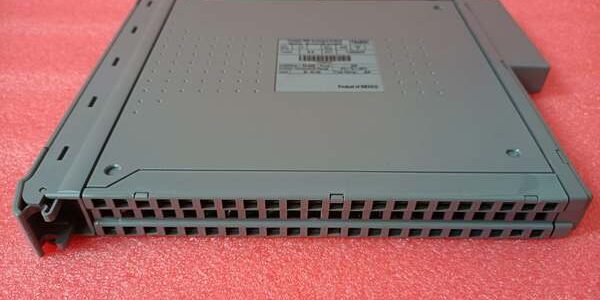
Product Core Brief
- Model: T8480C
- Brand: ICS Triplex (Rockwell Automation)
- Series: Trusted TMR Safety Control Series ⚠️ EOL — limited new surplus stock remaining
- Core Function: Generate triplicated 4–20 mA analog control signals for modulating control valves, positioners, and analog actuators via 2oo3 voted TMR logic
- Product Type: Backplane-mount TMR analog output I/O module
- Key Specs: 40 triplicated analog output channels | ±0.1% full span accuracy | Native SmartSlot interface for T8850 mixed-signal FTA | Condition: New Original Surplus
Product Introduction
The ICS Triplex is a single-slot TMR analog output card built for precision SIS and process control systems, using three parallel voted circuit paths to eliminate single-point analog channel failures. It pairs exclusively with the T8850 field termination assembly to isolate rack backplane wiring from live field analog cabling.This module outperforms older T8480 base variants via tighter ±0.1% span linearity and improved 1 ms resolution SOE timestamping. OEM reliability testing records an MTBF of 112,000 operating hours at a steady 40 °C cabinet ambient.
Key Technical Specifications
| Parameter | Value |
|---|---|
| Total Output Channels | 40 fully triplicated TMR analog output channels |
| Channel Power Grouping | 5 isolated banks of 8 channels each, galvanically separated |
| System Backplane Supply | 20 VDC to 32 VDC nominal 24 VDC |
| Standard Analog Output Range | 4 mA to 20 mA control signal, user configurable 0–20 mA secondary mode |
| Per-Channel Continuous Load Compliance | 0–750 Ω resistive actuator load maximum |
| Per-Channel Signal Accuracy | ±0.1% of full span, ±0.2% linearity across full operating temp |
| Overcurrent Protection | Latching electronic cutoff per channel, no replaceable field fuses |
| Event Logging Resolution | 1 ms Sequence of Events (SOE) timestamping for analog fault transients |
| Galvanic Isolation Rating | 2500 V impulse withstand channel-to-backplane barrier |
| Backplane Interface | SmartSlot gold edge connector, mechanical lock for T8850 FTA |
| Hot-Swap Support | Companion spare slot or shared SmartSlot chassis configurations |
| Operating Ambient Temp | 0 °C to +60 °C; storage -25 °C to +70 °C |
| Safety Certification | IEC 61508 SIL 3, TÜV AK6, UL/cUL, CE, IP20 cabinet-only |
| Physical Dimensions | 241 mm H × 30 mm W × 300 mm D; net weight 1.16 kg |
| Minimum Detectable Load Current | 1 mA for valid open/short circuit field line diagnostics |
Quality Control Process (Engineer’s Perspective)
- Incoming Verification: Cross serial numbers against Rockwell OEM batch manifests to reject counterfeit aftermarket copies. Visually scan PCB traces for cold solder joints, bent SmartSlot edge pins, and cracked front-panel channel status LED lenses.
- Live Functional Test: Insert module into a Trusted chassis test rack, connect a Fluke 115 regulated 24 VDC supply and matched T8850 FTA. Run a 24-hour soak cycle with 750 Ω resistive valve load simulators, log analog span accuracy and SOE timestamp integrity every 60 minutes.
- Electrical Parameter Test: Use a 500 V Megger to measure insulation resistance between isolated power groups and chassis ground; pass threshold is >10 MΩ. Verify per-channel overcurrent latch and auto-reset recovery behavior.
- Firmware Verification: Read and record installed firmware build number via DumpTrux utility; photograph front-panel DIP switch jumper positions for site configuration reference records.
- Final QC & Packaging: Place module inside static-dissipative poly bag. Affix dated QC Pass sticker listing measured insulation resistance and total soak test runtime before palletized storage.
Replacement Pitfall Guide
❗ Firmware Mismatch Risk: firmware build 5+ cannot hot-swap with chassis running build 4 without system.ini parameter adjustments. Unmodified older chassis trigger persistent analog channel vote mismatch critical faults.❗ Power Group Isolation Misconfiguration Risk: Jumping separate 8-channel power group feeds on the T8850 FTA erases galvanic separation, introducing cross-loop noise that distorts 4–20 mA analog valve position signals.❗ Cable Shield Grounding Incompatibility Risk: The chassis ground lug bonds to cabinet protective earth. Grounding field analog cable shields at both the FTA and actuator creates ground loops that inject low-frequency noise into control loops.❗ Power Supply Headroom Miscalculation Risk: A fully loaded draws 26 W field power plus 24 W backplane power at 24 VDC. Size cabinet power supplies with 20% overhead; underrated supplies drop voltage below 20 VDC and trigger SIL3 safe-state interlocks.❗ ESD Damage Risk: SmartSlot gold contacts remain exposed when the FTA is detached. Use a grounded anti-static mat during card swaps in low-humidity cabinet spaces; static discharge scratches plating and generates intermittent analog signal dropout faults.Keep these in mind and you’ll cut 90% of rework time.
Compatibility Matrix & Benchmarks
Compatibility Matrix
- (40-Ch Mixed Analog/Digital Output FTA) → : Direct Replacement — Native SmartSlot mechanical and electrical matching, zero wiring rework
- T8480 (Base Non-C Analog Output Module) → : Needs Adaptation — Chassis rack slot fits, firmware build revisions require analog span calibration re-tuning
- T8403 (Digital Input Module) → : Incompatible — Input signal conditioning circuits cannot drive analog actuator load impedances
Benchmarks
- Full 40-channel analog output state scan latency: 280 µs (simulated 750 Ω valve loads, 24 VDC nominal supply)
- Inter-group isolation resistance: >10 MΩ between separate 8-channel power banks (500 V Megger test)
- Continuous power consumption: 44 W average under full 40-channel 20 mA analog load split evenly across all five power groups




