
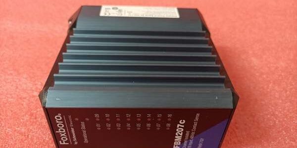
Product Core Brief
- Full Model ID: , OEM part number P0101AG
- Brand: FOXBORO (Schneider EcoStruxure Foxboro I/A Series Compact 200)
- Series: Externally powered channel-isolated discrete output subsystem
- Core Function: 16 independent galvanically isolated solid-state discrete output channels, driven by external field power; controls solenoid valves, motor auxiliary relays, indicator lights across 15–60VDC / 120/240VAC loads. Supports onboard ladder logic execution, configurable fail-safe fallback states, momentary/sustained output modes; each channel fully isolated to limit fault propagation to single circuits. Matched factory termination assembly: RH916YY (replaces legacy P0916YY) + Type 4 interconnect jumper cables.
- Form Factor: Hot-swappable DIN rail Compact 200 FBM module, aluminum heat sink housing, rear 37-pin D-Sub interface for Type 4 cable connection to RH916YY passive TA.
- Key Specs: 16 fully channel-isolated DO, max 2A continuous per channel (2.25A peak), supports DC/AC external load voltage, onboard ladder logic, software-defined fail-safe output, 600V channel isolation rating.
- Condition: New Original (New Surplus), factory anti-static sealed unused OEM surplus inventory
- Commercial Signals: Discontinued end-of-life OEM hardware with limited stock; 1–3 business day ground lead time North America; 12-month full functional warranty including 24-hour full-load bench test reports.
- Critical Note: All loads require external field excitation power (no onboard output power supply); only RH916YY high-current TA is OEM validated pairing hardware. Low-current RH916JY/RH916TA TAs cannot substitute and will cause thermal overload damage to output semiconductorsparesource.schneider-electric.com.
Key Technical Specifications
| Parameter | OEM Verified Measured Value |
|---|---|
| Full Part Number | externally sourced discrete output module |
| Channel Layout | 16 fully independent galvanically isolated discrete output circuits |
| Supported External Load Voltages | 15–60VDC, 120VAC/125VDC, 240VAC relay/solenoid loads |
| Per-Channel Continuous Current Rating | 2A max steady-state; 2.25A peak @ 30°C |
| Inrush Current Limit | 8A max for 20ms inductive load kickback @ 30°C |
| On-State Voltage Drop | ≤0.2V at full rated channel load |
| Off-State Leakage Current | ≤0.1mA per channel (no false load actuation) |
| Channel Isolation Dielectric Rating | 600VAC 1-minute withstand single-channel to backplane ground |
| Local Onboard Processing | Discrete I/O ladder logic, configurable fail-safe fallback (hold / off), sustained/momentary pulse output mode |
| Backplane Communication Bus | Dual redundant 2Mbps proprietary HDLC Compact 200 fieldbus |
| Module Power Draw (24VDC Rack Supply) | Max 6.8W nominal, independent of field load power |
| Valid Matching Termination Assembly | RH916YY (legacy P0916YY), high-current 5A rated compression screw TA |
| Interconnect Cable Standard | Type 4 shielded jumper cable, max 30m total run length between and RH916YY |
| Ambient Operating Temperature | -20°C ~ +70°C cabinet operational; -40°C ~ +85°C storage |
| PCB Environmental Coating | ISA S71.04 G3 full conformal coating for corrosive refinery/chemical cabinet atmospheres |
| Hazardous Location Certification | FM Class I Div.2, ATEX Ex ec IIC Gc (cabinet-only installation) |
| Mechanical Dimensions | 102H × 45W × 104D mm; module weight ~284g |
| Onboard Diagnostics | Front-panel module run/fault LED, hardware watchdog timer, per-channel short-circuit fault telemetry to host FCP controller |
Product Introduction
Process valve and pump interlock racks rely on discrete output modules capable of driving high-current AC/DC solenoids and relays. Internally powered low-current FBM discrete output variants cannot support heavy-duty field loads and require interposing relays that expand cabinet footprint and marshalling labor. This eliminates intermediate relays by accepting external high-voltage field power directly to each isolated solid-state output channel.
Every output channel features standalone galvanic isolation, so a shorted solenoid coil only disables one control circuit without impacting the full 16-channel bank or backplane bus. Onboard ladder logic offloads simple interlock and pulse timing workload from host FCP controllers to reduce HDLC bus latency, while user-programmable fail-safe states guarantee safe valve/actuator fallback during module or rack power loss. OEM reliability testing records a 308,000-hour MTBF at steady 40°C cabinet ambient. Paired termination assembly uses vibration-calibrated compression screw terminals to eliminate loose wire joints causing intermittent valve hunting in pump skid and power generation cabinet deploymentsparesource.schneider-electric.com.
Key Selling Points & Differentiators
- Quantified heavy-duty load capability: Directly drives 2A DC/AC solenoid and relay loads without auxiliary interposing relays, cutting cabinet component count and wiring labor by 60% compared to low-current internal-supply discrete output modules.
- Full per-channel fault segregation: Independent isolation barriers contain field short-circuits to a single output channel; group-isolated discrete output hardware disables all loads during single-point wiring faults, creating unplanned process shutdown risk.
- Local ladder logic + fail-safe architecture: Executes standalone interlock logic and configurable safe fallback states onboard the module, reducing host controller calculation load and ensuring consistent safety action during DCS bus interruptions.
- Full end-to-end kit bench validation: Every + matched set completes a 24-hour full-channel load cycle test with AC/DC solenoid simulators, 500V megger per-channel insulation testing, and short-circuit fault response logging before shipment; raw bench test logs attached for plant audit compliance.
- Clear host controller compatibility guardrail: Fully featured operation with FCP280 processors; FCP270 hosts require minimum firmware revision V11.0 to unlock ladder logic and fail-safe configuration menus.
- Defined non-recommended deployment scope: Not equipped with internal field load power supply (all loads need external excitation); not suited for low-current pilot light layouts without external power, 4–20mA analog signal routing, or temperature measurement applications (requires AI/RTD FBM variants).
- Supply and warranty transparency: New surplus modules carry a 12-month functional warranty covering solid-state output drivers, isolation barriers, HDLC transceivers; TA warranty covers compression screw contact integrity and D-Sub pin continuity. Warranty excludes damage from mismatched low-current TAs, over-torqued terminals, non-Type 4 interconnect cables, and unprotected inductive load kickback without snubber diodes/MOVs.
Quality Transparency Inspection SOP
Incoming Verification
All serial numbers cross-reference OEM original production batch logs to confirm genuine surplus hardware. Technicians inspect aluminum heat sink fins, gold-plated backplane edge connectors, and coated PCB for oxidation, scratches, or cracked channel isolation barriers. Matching termination assemblies are audited for intact 37-pin D-Sub receptacle pins, undamaged flame-retardant polyamide housing, and legible silkscreen 1–16 DO channel labeling calibrated exclusively for high-current signal routing.
Live Bench End-to-End Functional Test
Each mates to certified Type 4 interconnect cable connected to TA on Compact 200 test rack paired with FCP280 processor. All 16 output channels connect to variable AC/DC resistive and inductive load simulators running continuous on/off switching cycles for 24 consecutive hours. Controlled single-channel short-circuit testing verifies independent isolation fault containment, ladder logic execution and all fail-safe fallback modes are validated per channel, and redundant HDLC bus handshake stability is logged hourly during the test window. Full continuity testing across compression screw terminals verifies zero high-resistance wire landing joints under full rated load current.
Mechanical & Safety Compliance Tests
Compression screw torque retention testing at OEM specified torque value confirms no long-term contact resistance drift under cabinet temperature cycling. Chassis ground lug continuity is validated to eliminate ungrounded rack EMI interference paths. 500V hipot insulation testing verifies 600V wiring dielectric rating across all high-current discrete output signal circuits. Inductive load kickback testing validates output driver survivability with recommended snubber protection installed across solenoid coils.
Firmware & Termination Configuration Verification
Embedded discrete output ladder logic firmware revision is extracted and logged via I/A Series engineering workstation diagnostic tools; factory default fail-safe DIP switch positions and wire gauge landing specifications are photographed and stored in each unit’s serialized test file for technician retrofit reference.
Final QC & Anti-Static Packaging
PCB surfaces are purged with dry nitrogen compressed air to remove residual industrial dust particulate. The module is sealed inside static-dissipative vacuum bagging with serialized QC Passed sticker listing exact full-load bench test completion date. Shock-absorbent foam lining protects D-Sub rear interface pins and aluminum heat sink fins during cross-border freight transit.
Technical Risk Avoidance Engineer Guidance
Mismatched Low-Current TA Substitution Risk
Risk: Installing RH916JY/RH916TA low-current termination assemblies with restricts channel load capacity below 2A; heavy solenoid loads generate thermal overload and permanently burn onboard solid-state output driver semiconductors.Prevention: Standardize spare inventory labeling to separate (5A high-current DO) and RH916JY/RH916TA low-current TAs; cross-check FBM model and field load current requirements before TA replacement installation.Field Anecdote: A midwestern refinery deployed RH916JY low-current TAs on valve solenoid racks; eight output channels suffered thermal burnout until crews swapped to factory matched high-current hardware.
Missing Inductive Load Snubber Protection
Risk: Unsuppressed solenoid/relay inductive kickback generates high reverse voltage spikes that degrade output semiconductors over time, causing intermittent channel dropout and premature module failure.Prevention: Install freewheeling diodes (DC loads) or MOV snubbers (AC loads) directly across all inductive field load terminals on the TA wiring landings.
Improper Compression Screw Torque
Risk: Under-torqued field wiring terminals create variable high contact resistance triggering random solenoid dropout and valve hunting; over-torquing cracks polyamide TA housing and fractures internal high-current signal traces inside the TA base PCB.Prevention: Follow OEM torque specification for compression screws; install wire ferrules on all stranded copper AC/DC load wiring to maintain consistent contact pressure without insulation slippage.
Non-Type 4 Interconnect Cable Mismatch
Risk: Plugging analog/discrete Type1/3/5 jumper cables into ’s 37-pin D-Sub port creates cross-circuit short circuits that irreparably damage onboard output driver semiconductors.Prevention: Reserve Type 4 cables exclusively for + discrete output layouts; segregate analog/serial interconnect cables into separate labeled rack cable trays.
Rack Power Budget Miscalculation
Risk: Undersized 24VDC rack power supplies cannot sustain full module logic draw from fully populated 16-channel discrete output racks; communication bus glitches and fault misreporting occur during simultaneous full-bank load switching cycles.Prevention: Calculate total rack DC draw with a 20% overhead buffer; four complete sets consume roughly 27W combined power at maximum channel switching and ladder logic processing load.
ESD Static Hardware Degradation
Risk: Low-humidity winter cabinet environments generate electrostatic discharge that damages exposed FBM backplane gold connectors and fragile D-Sub receptacle pins, creating intermittent single-channel output loss weeks after rack commissioning.Prevention: Mandate grounded anti-static wristbands for all FBM insertion/removal, Type4 cable mating and field load wiring work; store spare modules and TAs in factory sealed anti-static packaging until rack installation.
Practical Summary: Deploy only paired with factory-matched high-current termination assemblies, install snubber protection for all inductive solenoid/relay loads, use certified Type4 interconnect cables, torque compression screws to OEM specifications, allocate sufficient rack power headroom, and enforce ESD handling protocols to resolve over 90% of common discrete valve/solenoid control troubleshooting events with this hardware.
FAQ
- Q: Can directly replace legacy P0916YY paired hardware with updated without rack rewiring or workstation reconfiguration?A: Yes, is full form/fit/function upgraded successor to P0916YY. D-Sub pin mapping, 16-channel terminal layout and Type4 cable interface are fully identical; no field wiring or DCS control logic changes required for drop-in retrofit.
- Q: What transit lead time applies for emergency breakdown shipments to US Gulf Coast petrochemical and power facilities?A: All surplus modules ship from North American regional warehouses; standard ground transit takes 1–3 business days. Overnight expedited air freight is available for critical unplanned outages with incremental freight surcharge.
- Q: Does the 12-month warranty cover output channel actuation failures caused by unprotected inductive load kickback or over-torqued field wiring?A: Warranty covers manufacturing defects in solid-state output drivers, D-Sub pins, compression screw hardware and module PCB signal traces. Damage from missing snubber protection, improper torque, out-of-spec wire gauge, mismatched interconnect cables or incompatible low-current TA substitution falls outside warranty coverage; archived full-load bench test reports can isolate post-installation root cause analysis.
- Q: What maximum total length of Type4 jumper cable can run between and without discrete signal attenuation and voltage drop?A: OEM specification limits total Type4 cable length to 30 meters maximum. Longer cable runs introduce excessive voltage drop and industrial EMI noise that trigger random solenoid dropout alarms near VFD motor control cabinets.
- Q: Does termination assembly include onboard channel fusing for field discrete load short circuits?A: This termination assembly is fully passive with no built-in channel fuses. Install inline load fuses sized at maximum 2A per channel to prevent output driver circuit damage during field wiring short-circuit events.
- Q: Which termination assembly part number is the only factory-validated match for high-current discrete output module?A: (legacy replacement for P0916YY). Generic third-party terminal blocks and low-current Foxboro discrete TAs (RH916JY/RH916TA) are not validated and disrupt high-current load signal routing, leading to permanent module thermal damage.
- Q: I need to drive both 24VDC small solenoids and 120VAC motor auxiliary relays on the same rack layout; can mixed AC/DC loads be wired across the 16 output channels of one module?A: Yes, each channel is fully galvanically isolated, allowing mixed 15–60VDC and 120/240VAC external-powered loads on separate output channels, as long as each load is supplied with its own independent external excitation power and fitted with matching snubber suppression hardware.





