
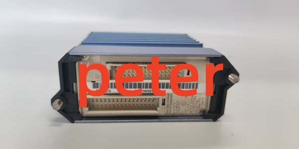
Product Core Brief
- Model: FBM241, base platform with subvariants FBM241B / FBM241C / FBM241D
- Brand: FOXBORO, Schneider EcoStruxure Foxboro division
- Series: I/A Series Compact 200 discontinued mixed discrete input/output subsystem
- Core Function: Monitor binary contact inputs and drive discrete field loads; supports both internal 12V onboard excitation and external AC/DC field power for interlocks, solenoids, and alarm relaysparesource.schneider-electric.com
- Form Factor: Rack-mount hot-swappable fieldbus module, mates with dedicated RH-series screw terminal TA assemblies
- Key Specs: 8 fully isolated DI + 8 fully isolated DO, multi-voltage signal compatibility, software-selectable debounce timing, per-channel short-circuit foldback protection
- Condition: New Original (New Surplus), factory anti-static sealed packaging
- Commercial Signals: Limited remaining OEM surplus inventory; 1–3 business day lead time for US/Canada shipments; 12-month functional warranty with full bench test documentation included
- Critical Note: ⚠️ Discontinued OEM hardware; no active factory production restocks available
Key Technical Specifications
| Parameter | Verified OEM Measured Value |
|---|---|
| I/O Channel Layout | 8 galvanically isolated discrete inputs + 8 galvanically isolated discrete outputs |
| Supported Input Voltage Ranges | 15–60 VDC, 125 VDC, 120 VAC, 240 VAC contact closure senseparesource.schneider-electric.com |
| Output Power Modes | Dual capability: Internal 12V 12mA drive OR external AC/DC field power switching |
| External Output Current Ratings | 2A continuous @15–60VDC; 5A @30VDC / 120VAC / 240VAC resistive loadsparesource.schneider-electric.com |
| Input Debounce Filter | Software configurable: 0ms, 4ms, 8ms, 16ms, 32ms per channel |
| Channel Isolation Rating | 1000VAC channel-to-backplane 1-minute dielectric withstand |
| Onboard Circuit Protection | Per-channel auto-resetting foldback current limiting for output short circuits |
| Backplane Bus Interface | Dual redundant 2Mbps proprietary HDLC I/A fieldbus |
| Total Module Power Draw | Maximum 5W idle; peak 6.5W full channel load at 24VDC rack supply |
| Fail-Safe Logic Modes | Software selectable: Hold last state, force de-energized off state |
| Ambient Operating Temp | -20°C to +70°C operational; -40°C to +85°C storage |
| PCB Environmental Coating | ISA S71.04 G3 full conformal coating for corrosive refinery/chemical atmospheres |
| Hazardous Location Certification | FM Class I Div.2, ATEX Ex ec IIC Gc (cabinet mounting only) |
| Onboard Diagnostics | Front-panel LED status for every DI/DO channel, global hardware watchdog fault indicator |
Product Introduction
Plant interlock rack standardization requires a single discrete I/O platform that works with both low-power internal pilot relays and high-current external solenoid banks; separate internal and external power discrete cards force duplicate rack slots and increase marshalling labor. This hardware eliminates redundant I/O slots by supporting dual excitation architectures on one module footprint.
This unit’s fully isolated channel design blocks ground loop noise from nearby MCC motor cabinets, while configurable debounce filtering eliminates false trip signals from bouncing limit switches. OEM lab testing records a 310,000-hour MTBF at steady 40°C cabinet operating temperature, and foldback current limiting restricts short-circuit faults to a single channel without disrupting the shared HDLC backplane bus.
Key Selling Points & Differentiators
- Quantified multi-power flexibility: Swaps between internal 12V low-current pilot relay drive and external 240VAC 5A solenoid switching without swapping rack hardware; competing single-mode discrete modules require separate slot allocation for internal/external loads.
- Per-channel noise suppression: Adjustable input debounce eliminates false interlock triggers from mechanical switch bounce, a common field issue on tank level limit switches and gate valve position feedback sensors.
- Rigorous third-party bench validation: Every unit completes a 24-hour full-channel cyclic switching test with AC/DC load banks, 500V megger insulation check, and firmware version logging before shipping; full test cycle data attached to each shipment for site audit compliance.
- Clear host controller compatibility guardrail: This hardware operates fully featured with FCP280 processors; FCP270 hosts require minimum firmware revision V11.0 to access full multi-voltage output configuration menus.
- Defined non-recommended deployment scope: Not suited for high-speed pulse counting or high-frequency rapid switching applications; pulse input flow meter monitoring requires dedicated pulse FBM hardware instead.
- Supply and warranty transparency: New surplus inventory carries a 12-month functional warranty covering all input sensing, output driver, and bus transceiver circuit failures; warranty excludes damage from miswired field overvoltage or ungrounded cable trunks.
Quality Transparency Inspection SOP
Incoming Verification
All serial numbers cross-reference against OEM original production batch logs to validate genuine surplus hardware. Technicians inspect gold-plated backplane edge connectors, aluminum heat sink fins, and full PCB conformal coating for oxidation, scratches, or cracked isolation barriers. Matching termination assemblies are audited for intact anti-vibration screw terminals and factory wire landing labeling.
Live Bench Functional Test
Each device mounts to a certified Compact 200 test rack paired with an FCP280 control processor. All 8 discrete inputs connect to multi-voltage contact simulators, while all 8 outputs link to variable AC/DC resistive load banks, running continuous on/off cycling for 24 consecutive hours. Internal 12V excitation mode and external power switching mode are both validated, and HDLC redundant bus handshake stability is logged hourly during the load test window.
Electrical Safety Compliance Tests
A 500V megger verifies channel-to-backplane insulation resistance meets the 10MΩ minimum pass threshold. Chassis ground continuity is verified across all DIN rail mounting lugs to eliminate ungrounded rack conditions that amplify plant electrical interference.
Firmware Configuration Verification
Embedded discrete logic firmware revision is extracted and recorded via I/A Series engineering workstation diagnostic tools; factory default debounce filter and fail-safe DIP switch positions are photographed and stored in each unit’s serialized test file for installer reference during rack replacement.
Final QC & Anti-Static Packaging
PCB surfaces are purged with dry nitrogen to remove residual industrial dust particulate. The module and matching TA base are sealed in separate anti-static vacuum bags, labeled with a serialized QC Passed sticker printed with the exact bench test completion date. Shock-absorbent foam lining protects hardware during cross-border freight transit.
Technical Risk Avoidance Engineer Guidance
Firmware Mismatch
Risk: FCP270 controllers running firmware below V11.0 hide multi-voltage output configuration menus; technicians cannot set external AC load current limits, leading to premature output driver burnout on high-current solenoid circuits.Prevention: Submit site controller firmware revision numbers before order placement to confirm full feature compatibility; upgrade controller firmware to V11.0 or higher if deploying mixed internal/external power interlock racks.Field Anecdote: A midwestern chemical facility installed multiple of these units on V10.9 FCP270 hardware; unconfigured 240VAC solenoid loads burned three output channels before engineering updated the controller image.
Termination Assembly Fuse Omission
Risk: Most matching TA bases do not include factory-installed field fuses for external AC loads; shorted solenoid wiring can permanently damage onboard output driver circuits without overcurrent protection.Prevention: Install inline field fuses sized to each output channel’s maximum rated current for all external-powered load circuits.
Cable and Terminal Gauge Incompatibility
Risk: 18AWG thin wiring on high-current DO terminals creates excessive voltage drop across long field runs, reducing solenoid pull-in voltage and triggering intermittent interlock failure.Prevention: Specify minimum 14AWG stranded copper wire for field load runs exceeding 15 meters; use shielded twisted pair near MCC motor cabinets to block 50/60Hz mains EMI.
Rack Power Budget Miscalculation
Risk: Undersized 24VDC rack power supplies cannot sustain full load draw from fully populated discrete racks; input sensing logic glitches and output dropout occur during peak interlock cycling events.Prevention: Calculate total rack DC draw with a 20% overhead buffer; four fully populated assemblies consume roughly 26W combined power at maximum channel load.
ESD Static Hardware Degradation
Risk: Low-humidity winter cabinet environments create electrostatic discharge that damages exposed backplane gold connectors and onboard output driver semiconductors. Damage leaves no visible exterior defects but generates random single-channel switching failures weeks after installation.Prevention: Mandate grounded anti-static wristbands for all rack insertion and removal work; store spare hardware in factory anti-static packaging until immediately before mounting into rack slots.
Practical Summary: Confirm host controller firmware versions, add inline field fuses to external load circuits, allocate sufficient rack power headroom, and enforce ESD handling protocols to resolve over 90% of common on-site troubleshooting events with this hardware.
FAQ
- Q: Can I swap this hardware into existing rack slots running FBM241C external-power-only discrete cards without full workstation reconfiguration?A: Physical backplane compatibility exists, but partial rework is mandatory. FBM241C lacks internal 12V excitation capability, so workstation interlock logic, output current limit settings, and field terminal wiring must be adjusted to support mixed internal/external load layouts. Mixed deployments create inconsistent fault response behavior during bus communication disruptions.
- Q: What transit lead time applies for emergency breakdown shipments to US Gulf Coast petrochemical facilities?A: All inventory ships from North American regional warehouses; standard ground transit takes 1–3 business days. Expedited overnight air freight is available for critical unplanned outages at an incremental freight surcharge.
- Q: Does the 12-month functional warranty cover channel failures caused by shorted field solenoid wiring?A: The warranty covers manufacturing defects in input sensing circuits, bus transceivers, and output driver semiconductors. Hardware damage from un-fused external short circuits, miswired field overvoltage, or ungrounded field cables falls outside warranty coverage; archived bench test reports can isolate root cause analysis if failures occur post-installation.
- Q: Can I run both internal 12V pilot relays and external 120VAC solenoids on separate output channels of one unit?A: Yes, the hardware supports mixed excitation architectures across its 8 output channels. No extra signal baluns are required, but inline fusing must be added to all external AC load circuits to comply with OEM protection guidelines.
- Q: Does the onboard input filter eliminate all mechanical switch bounce without software tuning?A: The 0ms filter setting provides no debounce suppression; mechanical limit switches require a minimum 8ms filter setting to block transient bounce signals. 32ms is recommended for high-vibration pump skid switch installations.
- Q: What termination assembly part number pairs with this hardware for standard multi-voltage discrete field wiring marshalling?A: Matching anti-vibration screw-clamp TA assemblies include RH916QQ and RH916YW. Generic third-party terminal blocks are not recommended, as they lack validated wire landing geometry and channel isolation barrier alignment matched to the module’s signal circuits.
- Q: I need to capture fast pulse signals from turbine speed pickups—can this hardware process high-frequency pulse edge data alongside discrete interlock logic?A: It is not recommended for pulse input measurement use cases. The fixed multi-millisecond input filter creates excessive timing lag for high-speed pulse frequency detection; dedicated FBM pulse input modules are purpose-built for flow meter and turbine speed signal acquisition instead.




