
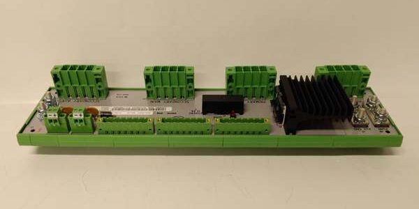
Product Core Brief
- Model: 5X00489G01 (legacy Westinghouse Ovation power distribution board)
- Brand: Emerson (Former Westinghouse Electric)
- Series: Ovation Q-Line Chassis Power Infrastructure
- Core Function: Rack-mounted power distribution board that splits incoming 24VDC supply into isolated MAIN controller bus and AUX IOP field power rails for Ovation chassis
- Product Type: Passive rack power splitter assembly with integrated heat sink and multi-group screw terminal banks
- Key Specs: 24VDC nominal input | 20A combined total current rating | segregated MAIN/AUX output terminals | redundant dual input feed support
- Note: Discontinued OEM hardware; new surplus stock available, exclusive fit for Ovation Q-Line rack chassis only
Key Technical Specifications
| Parameter | Value |
|---|---|
| Nominal DC Input Voltage | 24 VDC ±15% industrial cabinet supply |
| Max Combined Total Current | 20 A continuous across MAIN + AUX output groups |
| MAIN Controller Bus Output | Dedicated terminal bank for Ovation CPU and communication cards |
| AUX IOP Field Bus Output | Isolated terminal bank for all IOP personality module field power |
| Redundancy Input Support | Dual parallel 24VDC input lugs for redundant power supply pairing |
| Termination Hardware | M6 high-current power lugs; M3 signal screw terminals, 0.5–4mm² wire capacity |
| Thermal Dissipation | Integrated aluminum extrusion heat sink for steady-state full-load cooling |
| Overcurrent Protection | External chassis branch circuit fusing required; PCB trace current limited to 20A max |
| Operating Temperature | -40°C to +70°C operational; -40°C to +85°C storage |
| Environmental Grade | ISA S71.04 G3 corrosive gas resistant, full PCB conformal coating |
| Physical Dimensions | 200mm L × 150mm W × 60mm D; net weight 1.2 kg |
| Vibration & Shock | 1mm pp (2–13.2Hz); 0.7g constant (13.2–150Hz); 10g half-sine 11ms shock |
| Hazardous Certifications | FM Class I Div2, ATEX Ex ec IIC Gc (Zone 2 cabinet mounting only) |
| Compatibility Restriction | Mechanical form factor and terminal pinout exclusive to Ovation Q-Line racks; zero DeltaV cross-system compatibility |
Product Introduction
This passive power distribution hardware acts as the central power junction inside Ovation Q-Line chassis, separating critical controller power from field IOP power to contain wiring short-circuit faults away from core control logic. Dual input lugs allow two matching rack power supplies to feed the board in parallel for fault-tolerant boiler and turbine control systems.Segregated terminal banks eliminate cross-contamination between low-noise controller bus power and high-transient field I/O loads, cutting analog signal jitter caused by solenoid and valve switching transients. The attached aluminum heat sink stabilizes PCB surface temperature during continuous full 20A load operation in poorly ventilated cabinet enclosures.
QA & Testing SOP
- Incoming Inspection: Cross-reference serial numbers against OEM factory batch logs; inspect high-current M6 lugs for corrosion and heat sink mounting hardware for loose fasteners. Reject units with cracked PCB substrate or stripped terminal screw threads.
- Live Load Distribution Testing: Mount inside matching Ovation Q-Line chassis, feed dual redundant 24VDC input via Fluke 115 multimeter. Load MAIN and AUX rails to combined 20A rated current for 24 hours; log voltage drop across power lugs and PCB traces.
- Redundancy Feed Stress Test: Activate single power supply loss while monitoring both output rails to validate zero voltage dip during redundant source transfer.
- Continuity & Isolation Test: Verify complete electrical separation between MAIN and AUX terminal banks; confirm unbroken conductive paths between input lugs and each output terminal group.
- Final QC & Packaging: Purge PCB and heat sink surfaces with dry nitrogen to remove industrial particulate contamination; seal unit in static-shield bag with printed test report capturing full-load voltage drop and thermal stability data.
Installation Pitfalls & Guide
❗ ESD Component Failure Risk: Ungrounded contact with PCB power traces can degrade conformal coating and create hidden high-resistance joint faults; full chassis power shutdown labor costs exceed $2,900. Always attach a grounded anti-static wrist strap to cabinet safety ground before handling the board.❗ Zone 0/1 Hazardous Area Misapplication: The distribution board only holds Div2 safety certification. Deploying it in Zone 0 or Zone 1 flammable gas cabinets voids all safety approvals and creates ignition hazards.❗ Undersized Input Power Wiring: 12AWG or smaller input cable generates excessive voltage drop under peak 20A load, triggering undervoltage fault alarms on Ovation controllers during full IOP rack startup.❗ Mixed MAIN/AUX Terminal Miswiring: Routing field IOP loads to MAIN controller terminals introduces severe transient noise that corrupts controller scan data and triggers unexpected safety interlock trips.❗ Missing External Branch Fusing: The PCB carries no built-in overcurrent fusing; omitting upstream circuit breakers creates risk of permanent PCB trace burnout during field wiring short events.
4-Step Replacement Guide
- Pre-install: Execute full chassis lockout/tagout and shut down both redundant rack power supplies; photograph all M6 input lugs and M3 MAIN/AUX terminal wiring assignments for rebuild reference. Hot-swap is not supported for this power splitter board.
- Removal: Disconnect all high-current power lugs and field terminal wiring; unfasten chassis mounting screws, slide the unit horizontally out of the Q-Line rack cavity.
- Install: Secure the new unit to chassis mounting brackets with OEM torque values; reterminate dual redundant 24VDC input feeds to M6 lugs, split controller and IOP loads to their designated MAIN/AUX terminal banks per pre-install photos. Torque all power lug fasteners to specified OEM torque rating.
- Power-on Test: Release lockout/tagout and energize redundant rack power supplies; monitor MAIN and AUX rail voltage via Ovation diagnostic console for 2 continuous hours; simulate single power supply dropout to confirm bumpless load transfer without controller scan interruption.
FAQ
Q: Can this board operate with only one single rack power supply instead of dual redundant feeds?A: Yes, it supports single-source 24VDC input wiring, but the system loses fault tolerance. Critical boiler/turbine control racks require dual parallel power feeds connected to both input lugs for uninterrupted operation.Q: Does hot-swapping this power distribution board work while chassis power stays energized?A: No. All MAIN and AUX power rails run live through the board; removal while powered cuts power to every controller and IOP module simultaneously, triggering full plant process interlock trips. Full chassis power shutdown is mandatory for replacement.Q: What hardware fault patterns signal a failed unit?A: Excessive voltage drop under moderate load, localized hotspots on PCB traces or heat sink, intermittent power loss to all MAIN or AUX terminals, corroded high-current lugs with rising contact resistance, or stripped terminal screw threads that cannot maintain torque.Q: Can this power splitter board be installed inside DeltaV M/S-series I/O racks?A: No, mechanical mounting geometry, chassis depth, and terminal bus pinout are exclusively designed for Ovation Q-Line rack infrastructure; physical fitment to DeltaV racks is impossible without custom non-OEM adapter hardware that voids all safety certifications.Q: What warranty coverage applies to new surplus stock?A: A 12-month limited warranty covers PCB copper traces, terminal lug hardware, and heat sink factory assembly defects. Damage from ESD mishandling, under-torqued power lugs causing high-resistance joints, undersized input wiring voltage drop, or deployment in unapproved hazardous zones is excluded from coverage.Q: Is there a maximum current limit that can be routed solely to the AUX IOP terminal bank?A: Up to 12A continuous load can be assigned to the AUX rail, with the remaining 8A allocated to the MAIN controller rail to stay under the combined 20A total current rating of the board. Exceeding this split ratio creates thermal overload on the PCB power traces.




